Socket for an electronic device

a technology for electronic devices and sockets, applied in the direction of fixed connections, coupling device connections, instruments, etc., can solve the problem of sockets becoming sources of hea

Inactive Publication Date: 2007-11-22
CENTIPEDE SYST
View PDF31 Cites 138 Cited by
  • Summary
  • Abstract
  • Description
  • Claims
  • Application Information

AI Technical Summary

Benefits of technology

[0010]One or more embodiments of the present invention satisfy one or more of the above-identified demands. In particular, one embodiment of the present invention is a socket useful to contact an electronic device, the socket comprising: (a) one or more contactor holder plates including one or more first through holes having a first hole cross sectional area, and one or more second through holes having a second hole cross sectional area; (b) one or more first contactors having a body with a first body cross sectional area disposed in the first through holes; (c) one or more second contactors having a body with a second body cross sectional area disposed in the second through holes; and (d) a heat sink in thermal contact with one or more of the one or more contactor holder plates; wherein a first ratio of the first hole cross sectional area to the first body cross sectional area is different from a second ratio of the second hole cross sectional area to the second body cross sectional area.
[0011]In addition, another embodiment of the present invention is a socket useful to contact an electronic device, the socket comprising (a) one or more electrically conductive contactor holder plates including one or more first through holes having a first hole cross sectional area, and one or more second through holes having a second hole cross sectional area; (b) one or more first contactors having a body with a first body cross sectional area disposed in the first through holes; and (c) one or more second contactors having a body with a second body cross sectional area disposed in the second through holes; wherein a ratio of the first hole cross sectional area to the first body cross sectional area is greater than 1.4 times a ratio of the second hole cross sectional area to the second body cross sectional area.

Problems solved by technology

Further, at higher levels of current, the socket becomes a source of heat due to current flowing through the contact resistance of each pin.

Method used


Image

  • Socket for an electronic device
  • Socket for an electronic device
  • Socket for an electronic device

Examples


Embodiment Construction

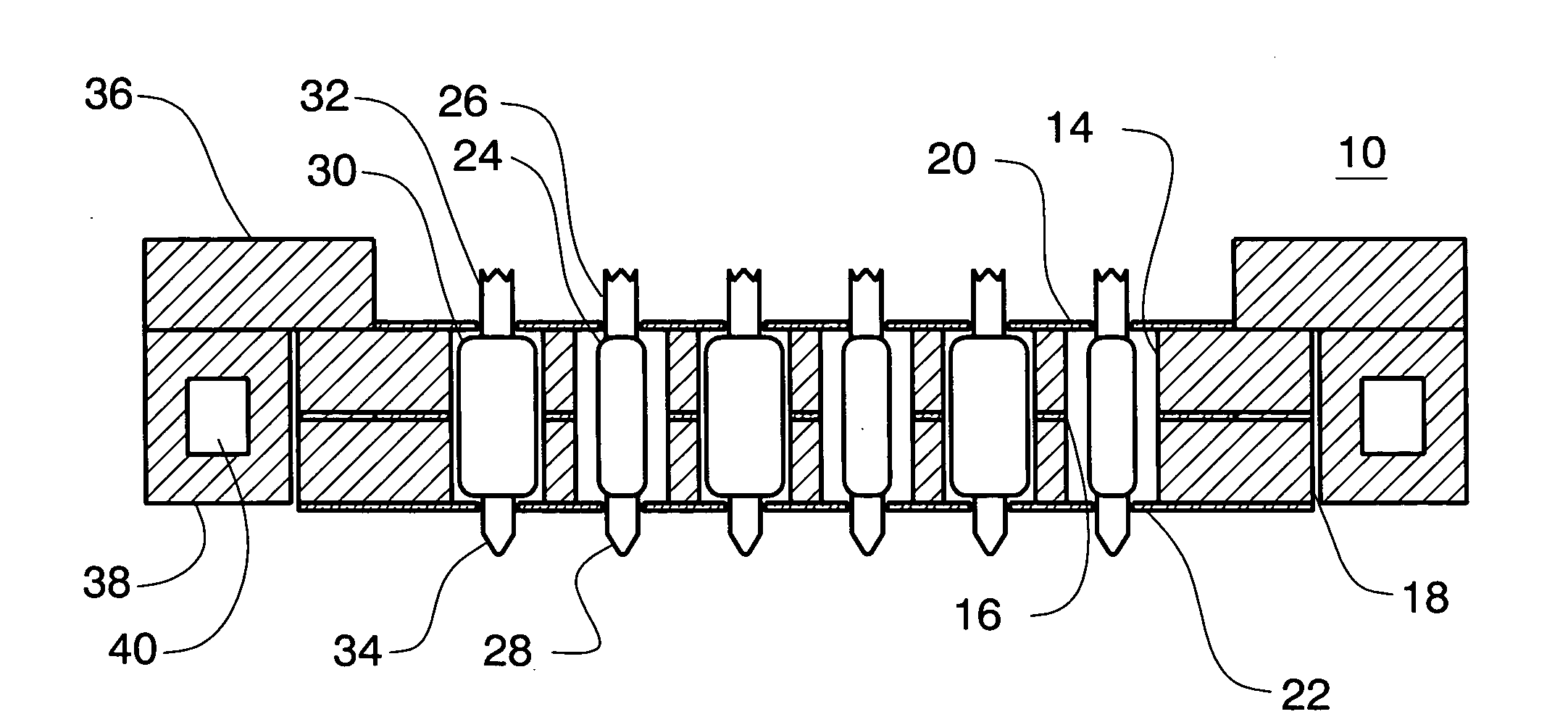
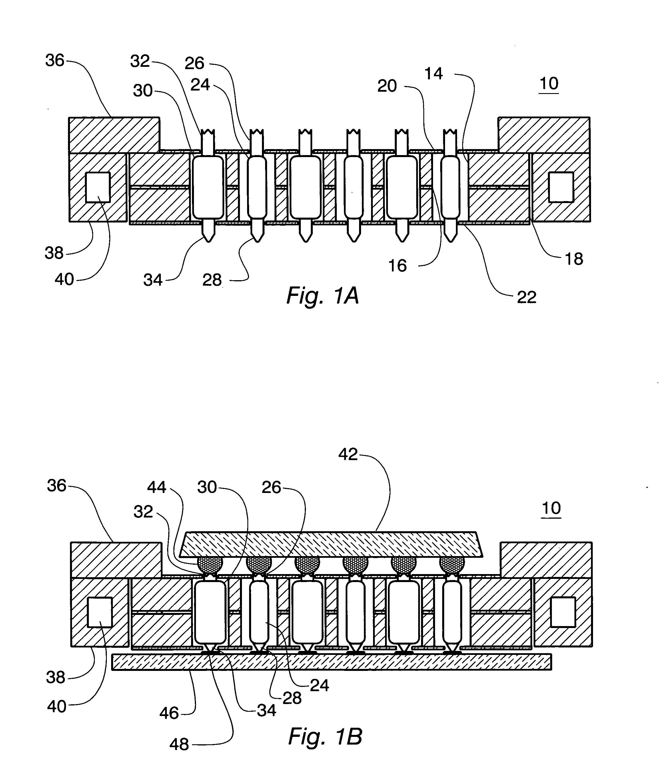
[0023]FIG. 1A shows a cross sectional view of socket 10 that is fabricated in accordance with one or more embodiments of the present invention. In accordance with one or more embodiments of the present invention, socket 10 can be used, among other things, as a socket for contacting an integrated circuit (“IC”) or other microelectronic or electronic device.

[0024]As shown in FIG. 1A, socket 10 comprises contactors in the form of a plurality of spring probes 24 and spring probes 30 that are held in circular, cylindrical through holes in contactor holder plates 14 and 18 by dielectric sheets 20 and 22. As shown in FIG. 1A, dielectric sheets 20 and 22: (a) have holes for spring pins of the spring probes (as is well known, the term spring pin refers to a pin that protrudes from a spring probe); (b) prevent spring probes 24 and spring probes 30 from making contact with contactor holder plates 14 and 18; and (c) provide insulation between socket 10 and any device or test board to which sock...


PUM


Abstract

One embodiment of the present invention is a socket useful to contact an electronic device, the socket including: (a) one or more contactor holder plates including one or more first through holes having a first hole cross sectional area, and one or more second through holes having a second hole cross sectional area; (b) one or more first contactors having a body with a first body cross sectional area disposed in the first through holes; (c) one or more second contactors having a body with a second body cross sectional area disposed in the second through holes; and (d) a heat sink in thermal contact with one or more of the one or more contactor holder plates; wherein a first ratio of the first hole cross sectional area to the first body cross sectional area is different from a second ratio of the second hole cross sectional area to the second body cross sectional area.

Description

[0001]This patent application relates to U.S. Provisional Application No. 60 / 801,304 filed May 18, 2006 from which priority is claimed under 35 USC §119(e), and which provisional application is incorporated herein in its entirety.TECHNICAL FIELD OF THE INVENTION[0002]One or more embodiments of the present invention relate to a socket for an electronic device such as a microelectronic device, and more particularly to a socket for supplying high current and high frequency electrical currents to high performance microelectronic devices, for example, and without limitation, integrated circuits (“ICs”).BACKGROUND OF THE INVENTION[0003]Sockets are used widely in the electronics industry to mount and connect microelectronic devices such as semiconductor integrated circuits (“ICs”) to electronics systems of various sorts—as is well known, a socket is used to connect terminals on a device to corresponding contacts on a printed circuit board or other electrical interconnection means. In addit...

Claims


Application Information

Patent Timeline
Patent Type & Authority Applications(United States)
IPC IPC(8): H01R12/00
CPCG01R1/045G01R1/0466G01R1/0483H01R12/52H01R2201/20G01R1/06738H01R13/2471
Inventor DI STEFANO, THOMAS H.
Owner CENTIPEDE SYST
Why Eureka
Try Eureka