Sectional golf tee

a golf tee and sectional technology, applied in the field of golf tees, can solve the problems of inconvenient manual realignment of tee pieces in the field, lack of convenience of handling a single piece of tee in its ground penetration, and inability to provide a solution for aligning component tees

Inactive Publication Date: 2007-11-22
JUNG MAN YOUNG
View PDF6 Cites 9 Cited by
  • Summary
  • Abstract
  • Description
  • Claims
  • Application Information

AI Technical Summary

Benefits of technology

[0010] An object of the present invention is to provide a sectional golf tee having two distinctive states, a sustainable tee shape under normal handlings and split tee halves in compliance with a club movement with the distinctive states being repeatable perfectly and easily.

Problems solved by technology

Thus, it lacks the convenience of handling a single piece of tee in its ground-penetration before the tee parts must be carefully aligned in preparation of propping up a ball to hit.
In view of this fact, the above tee fails to provide a solution to align component tees in exactly the same repeatable way when the tee is reused.
And manually realigning tee pieces in the field would be annoying.
Specifically, these pivotable connections might reduce the impact resistance when they are hit in a certain way yet do not eliminate the resistance to the golf swing and broken tees.

Method used


Image

  • Sectional golf tee
  • Sectional golf tee
  • Sectional golf tee

Examples


first embodiment

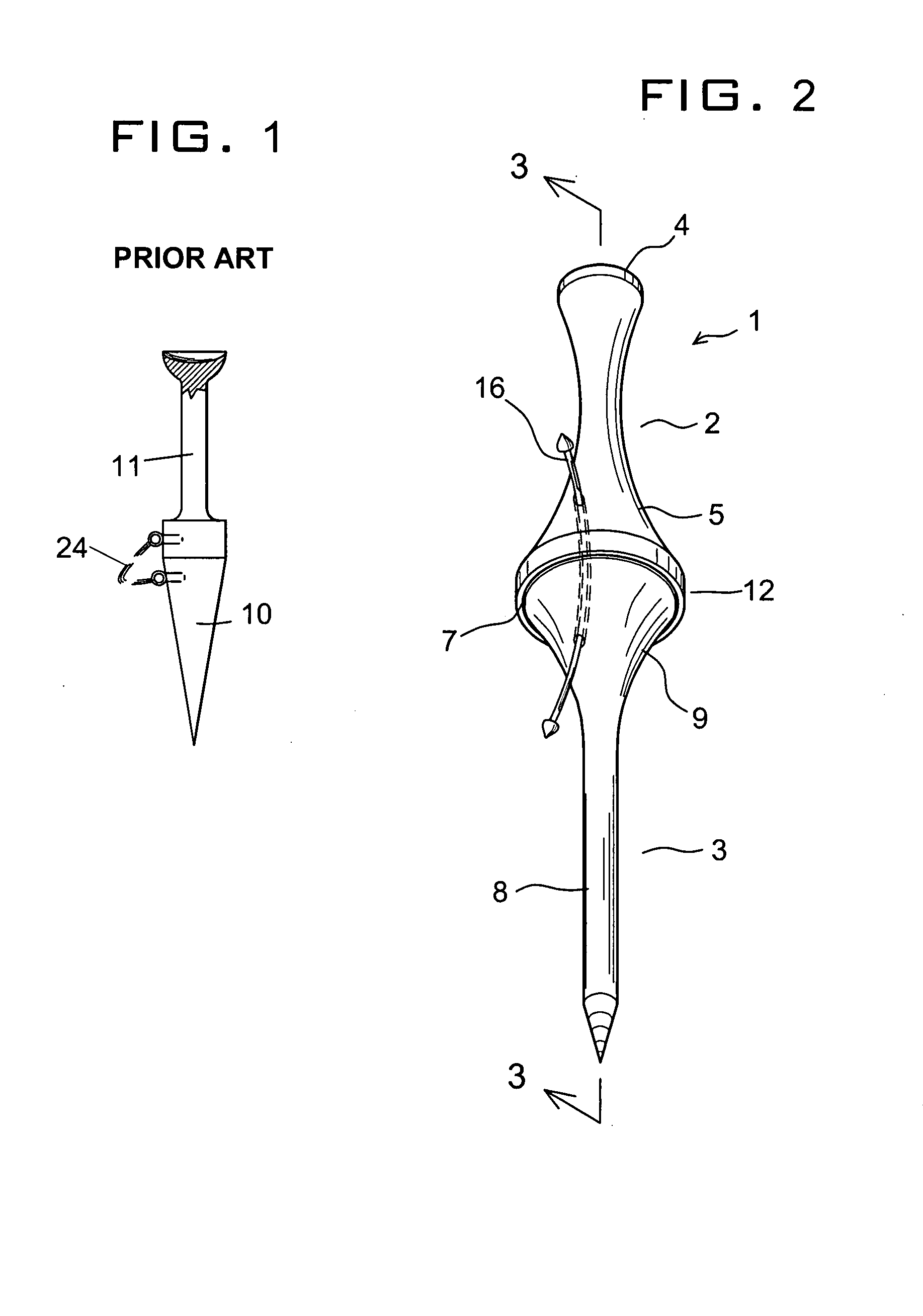
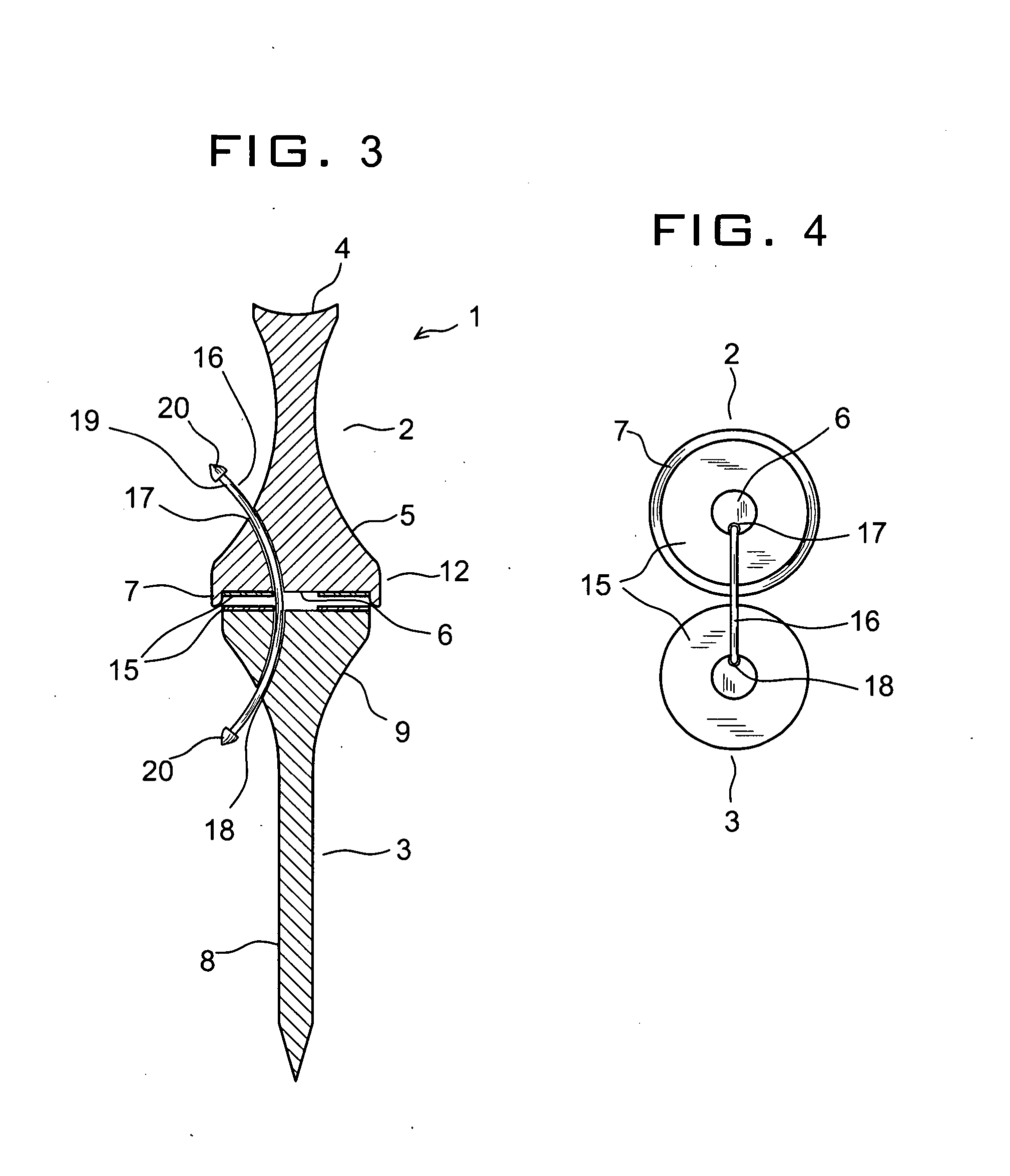
[0025] With reference to FIGS. 2 and 3, a golf tee 1 according to the present invention generally comprises a longitudinal tee top 2 and a tee base 3, which is mated to the tee top 2 and extends along a common longitudinal axis. Both tee members 2 and 3 are formed of a rigid material including wood and plastic to have round sidewalls. They may be made of the same material or a hybrid of two different materials as needed.

[0026] The tee top 2 is constricted in the middle to provide an easy grip for facilitating its handling at the teeing ground. Top end 4 of the tee top 2 is concave to conform to a bottom section of a golf ball, not shown. The tee top 2 has a cone section 5 at it lower end, which has a flat bottom 6. The bottom 6 has a protrusion extending downwardly and circumferentially to form a short annular wall 7 adapted to mate two tee members 2 and 3 in a concentric relation. The height of the wall 7 is set so that it is just enough to assist in aligning the tee members 2 and ...

second embodiment

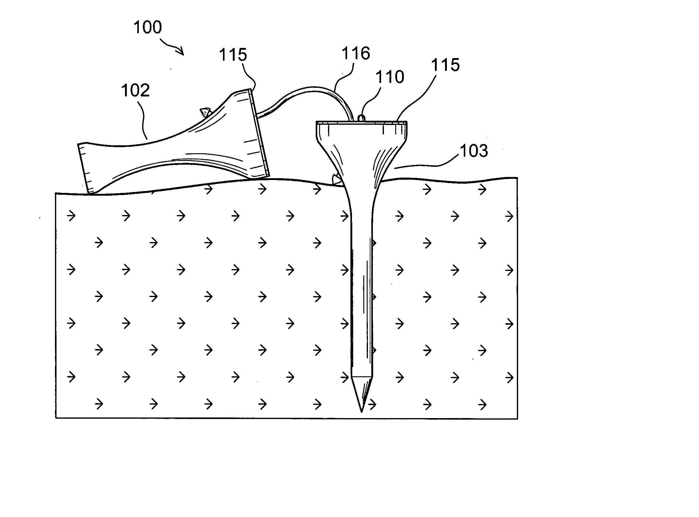
[0034]FIG. 5 shows a sectional golf tee 100 of the present invention wherein an alternative centering means is used between a tee top 102 and a tee base 103, which can be mated to the tee top 102 extending along a common longitudinal axis.

[0035] The tee top 102 is constricted in the middle to provide an easy grip for facilitating its handling at the teeing ground. Top end 104 of the tee top 102 is concave. The tee top 102 has a cone section 105 at it lower end, which has a generally flat bottom 106. The bottom 106 is recessed upwardly in the center to form a shallow cave 107 adapted to mate two tee members 102 and 103 in a concentric relation. The depth of the cave 107 is set so that it is just enough to assist in aligning the tee members 102 and 103 but does not hinder a lateral flipping action of the tee top 102 away from the tee base 103.

[0036] The tee base 103 takes the form of a pointed peg 108 for an easy penetration into the ground and has an inverted cone section 109 at its...


PUM


Abstract

A sectional golf tee is provided comprising a lower tee half which is made of a rigid material for penetrating the ground, and an upper tee half which is mechanically and/or magnetically mated to the lower tee half along a common longitudinal axis to elevate a golf ball with a loose cord keeping the halves within a retrieving distance. To an omnidirectional hitting impact at the ball the upper tee half is totally compliant by its physical separation from the lower tee half overcoming the mechanical and/or magnetic attraction with zero resistance to the club movement.

Description

BACKGROUND OF THE INVENTION [0001] A. Field of the Invention [0002] The present invention relates to a golf tee. More particularly, the present invention relates to a component golf tee totally collapsible to have zero interference with a club swing. [0003] B. Description of the Prior Art [0004] A golf tee works to give a considerable advantage for drive shots by elevating a golf ball to a convenient height. The most common type of golf tee is a simple wooden peg with a flared top, which has been in use since the 1920s. Articulated golf tees were also introduced in search of a solution to damages to the tees from the clubs striking the same along with balls. [0005] U.S. Pat. No. 1,623,119 to Kearney discloses in its FIG. 6 embodiment a link 24 for connecting golf tee halves 10 and 11 flexibly secured at two eyes 25 and 26. The above patent suggested no dedicated means to positively hold the tee halves together but the upper part 11 rested flat on the lower part 10, and the flexibili...

Claims


Application Information

Patent Timeline
Patent Type & Authority Applications(United States)
IPC IPC(8): A63B57/00
CPCA63B57/0018A63B2210/50A63B2209/08A63B57/005A63B57/12A63B57/10A63B57/13
Inventor JUNG, MAN-YOUNG
Owner JUNG MAN YOUNG
Why Eureka
Try Eureka