Fluid flow distributor apparatus for gas turbine engine mid-frame section

a distributor apparatus and gas turbine engine technology, applied in the direction of lighting and heating apparatus, machines/engines, stators, etc., can solve the problems of not providing the most efficient overall gas turbine engine, and not effectively providing the desired resolution

Inactive Publication Date: 2007-11-29
SIEMENS ENERGY INC
View PDF8 Cites 46 Cited by
  • Summary
  • Abstract
  • Description
  • Claims
  • Application Information

AI Technical Summary

Problems solved by technology

Design optimization for conversion of dynamic pressure to static pressure may not provide for overall optimization when other functional objectives, such as efficient cooling of the transitions, are taken into account.
That is, optimizing the annular diffuser to provide the most efficient conversion without considering alternatives that would more efficiently cool the transitions may not provide the most efficient overall gas turbine engine.
However, radial diversion of a substantial portion of compressed fluid from an annular diffuser, without more, may not effectively provide a desired resolution when the fluid flow from the compressor is desired to be used to cool the transitions.
Particularly, when there is a relatively long expanse of transition disposed aft of a radially split annular diffuser, given the tendency of fluid flow from such diffuser to deviate radially and forward, toward the combustion chambers' intakes, such an approach does not provide a balanced cooling fluid flow across the length of such transition.
This may necessitate implementation of transition cooling approaches that are relatively costly on a capital and / or an operational basis.

Method used


Image

  • Fluid flow distributor apparatus for gas turbine engine mid-frame section
  • Fluid flow distributor apparatus for gas turbine engine mid-frame section
  • Fluid flow distributor apparatus for gas turbine engine mid-frame section

Examples


Embodiment Construction

[0015]To the extent that an effective and balanced cooling fluid flow from the compressor provides adequate cooling, the additional capital and / or operational costs of utilizing or adding other cooling approaches is reduced or eliminated.

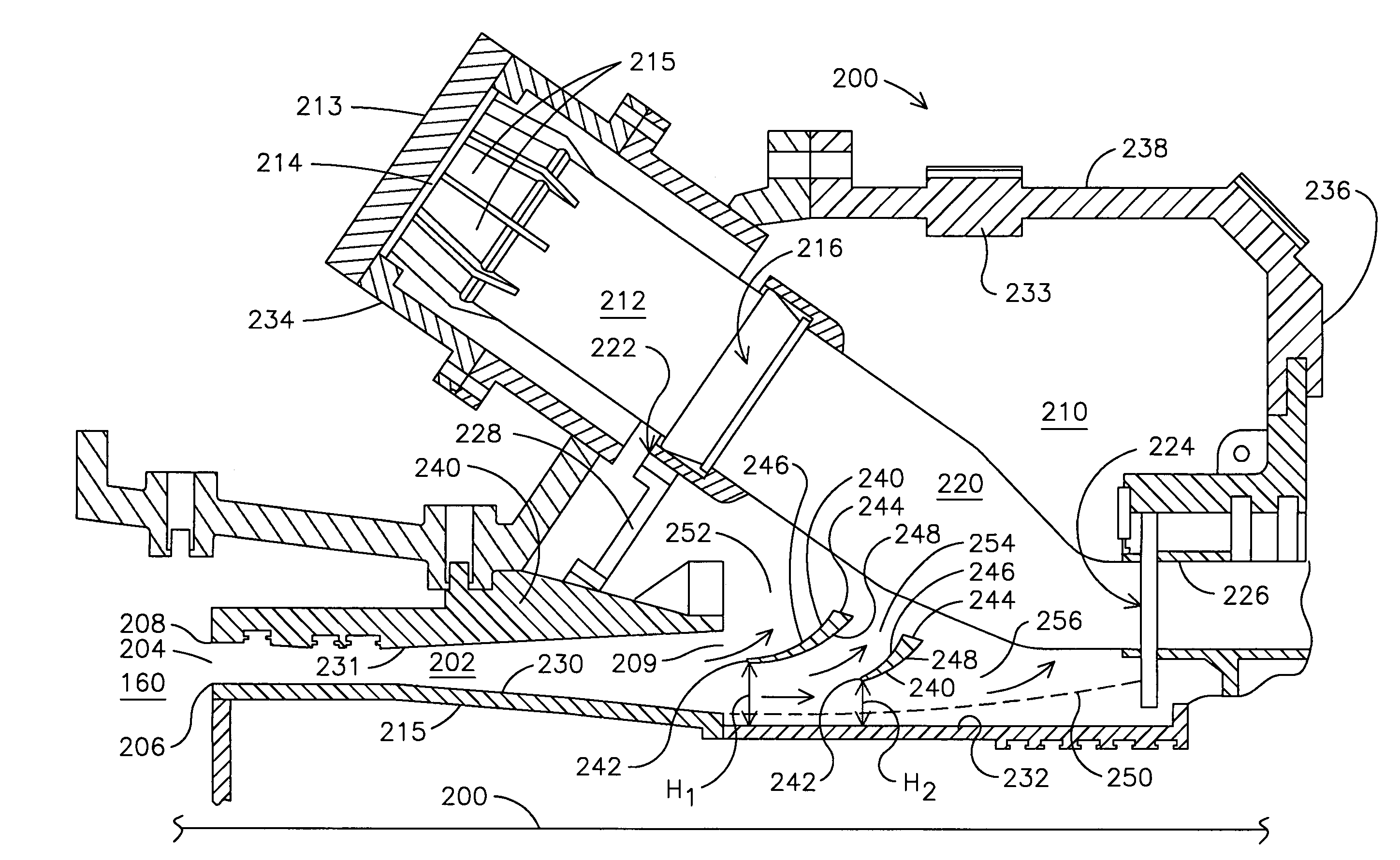
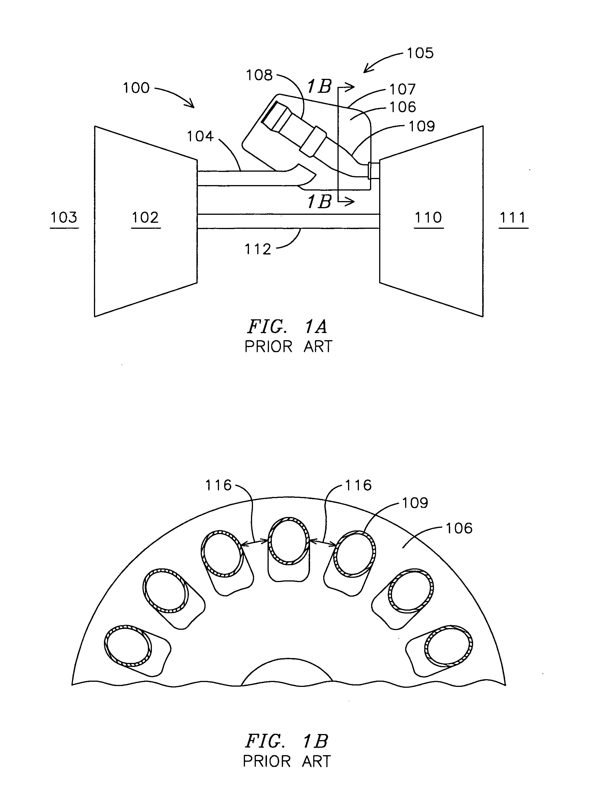
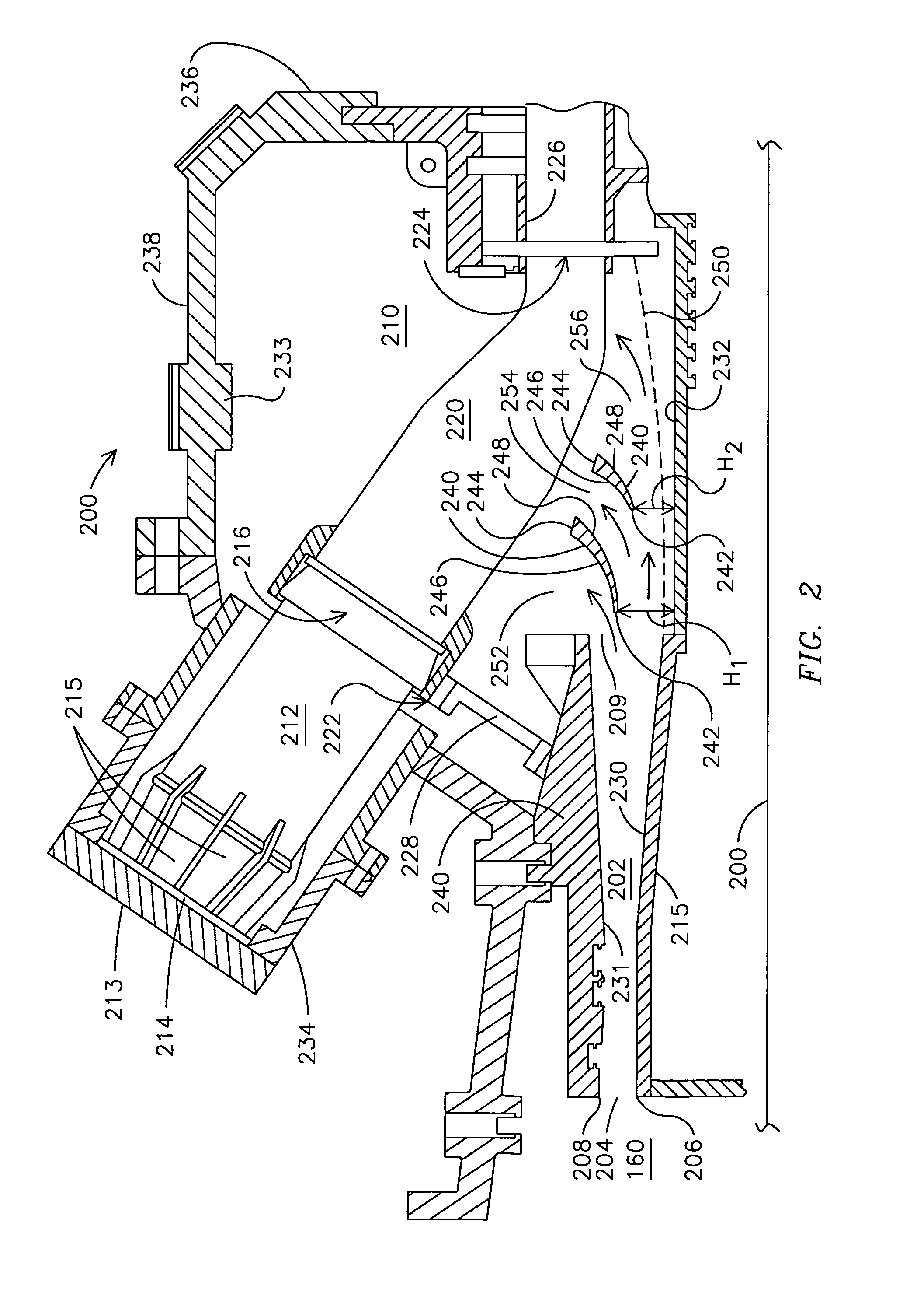
[0016]Notwithstanding the features of known diffuser flow-splitting approaches, when fluid from a compressor is desired to cool the transition, there is a need for an appropriately designed combination of fluid-flow-directing elements to attain a reliable, desired balancing of overall fluid flow efficiency and of transition cooling. As disclosed in the following sections, the present invention provides a fluid flow distributor comprising fluid-flow-directing flow splitters in a mid-section plenum that are effective to achieve this desired balance, toward providing a generally more efficient gas turbine engine. That is, the present invention advances the art by providing a solution to the dual, potentially conflicting issues of cooling of transitions...


PUM


Abstract

A plenum (210) in a gas turbine engine mid-frame section (200) comprises one or more annular flow splitters (240) spaced from an inboard annular wall (232) that partition air flow flowing from a compressor into two or more portions of flow having different vectors. This provides for an improved balancing between supplying air to compression chamber intakes more directly and to transitions to aid in convective cooling. When an annular diffuser (202) is spaced between the compressor and the plenum (210), the flow splitters (240) may provide an additional diffusion action. When no annular diffuser is so provided, the flow splitters (452, 454, 456) are effective to diffuse the air flow. Embodiments include those in which an annular diffuser (304) is relatively shorter and there is a longer axial expanse in the plenum (320) for flow splitters (350, 352, 354, 356).

Description

FIELD OF THE INVENTION[0001]The invention generally relates to a gas turbine engine, and more particularly to the mid-frame section of such an engine including a diffusion zone.BACKGROUND OF THE INVENTION[0002]In gas turbine engines, air is compressed at an initial stage, then is heated in combustion chambers, and the hot gas so produced drives a turbine that does work, including rotating the air compressor.[0003]To achieve a good overall efficiency in a gas turbine engine, one consideration is the reduction of losses of fluid pressure, such as due to friction and turbulence, between the compressor and the intakes of the combustion chambers. In a common gas turbine engine design, compressed air flows from the compressor, through an annular diffuser, into a plenum in which are positioned transitions and other components, and then from the plenum into the intakes of combustion chambers.[0004]Generally, a diffuser converts a high velocity, low pressure fluid flow into a low velocity, h...

Claims


Application Information

Patent Timeline
Patent Type & Authority Applications(United States)
IPC IPC(8): F02C1/00
CPCF01D9/023F05D2240/12F23R3/26F02C7/12
Inventor DAWSON, ROBERT W.
Owner SIEMENS ENERGY INC
Why Eureka
Try Eureka