
Industrial Robot

Inactive Publication Date: 2007-11-29
SCHEIBLE GUNSTREETCAR +2
View PDF9 Cites 4 Cited by
  • Summary
  • Abstract
  • Description
  • Claims
  • Application Information

AI Technical Summary

Benefits of technology

[0013] A primary object of the present invention is to provide a wireless power supply for a tool of an industrial robot that overcomes the drawback

Problems solved by technology

The fact is that due to such complex twisting and bending of the cabling the individual cable parts of the cabling are often worn out or begins to operate in failure.
The appearances of a loose contact is often difficult to detect and even more difficult to repair.
Besides, the cabling arranged on the outside of the robot is trespassing the working space and sometimes blocking the performance of the robot.
Still the cabling is worn and sometimes torn by this twisting movement and will sooner or later fail to operate.
The replacement of the cabling inside the robot arms is complicated and puts the robot out of production for a considerable time.
The swivel solution has a first drawback of adding weight and length to the upper arm.
Thus the swivel device will harm the performance of the robot.
A second drawback of the swivel unit is the contact problem of the slip rings.
There will always be infinitesimal moments of non contact, which will disturb the communication with the tool.
This lead to higher friction and to a further decrease of the performance of the robot.
The slip rings and the contact shoes must be made of high quality material which is expensive.
Thus even if the swivel solves the problem of the cabling being worn by twisting there is still a contact problem in the swivel itself or in the connecting interface.
The large core parts are expensive to produce and the ferrite material is very brittle.
Thus this known device is unsuitable for use in harsh environment.
Thus a small collision force on the tool would completely destroy the effectiveness of the known transformer.
For powering a tool of an industrial robot the rotating ring transformer arrangement of the latter document is inconvenient because the need of a battery that makes the tool heavier.
Furthermore for higher power levels and at the proposed frequency range, the intermittent controlled resonant operation results in significant harmonics, and modulation which are not allowed by regulations due to disturbance of RFID (radio frequency identification), communication and radio equipment.

Method used


Image

  • Industrial Robot
  • Industrial Robot
  • Industrial Robot

Examples


Embodiment Construction

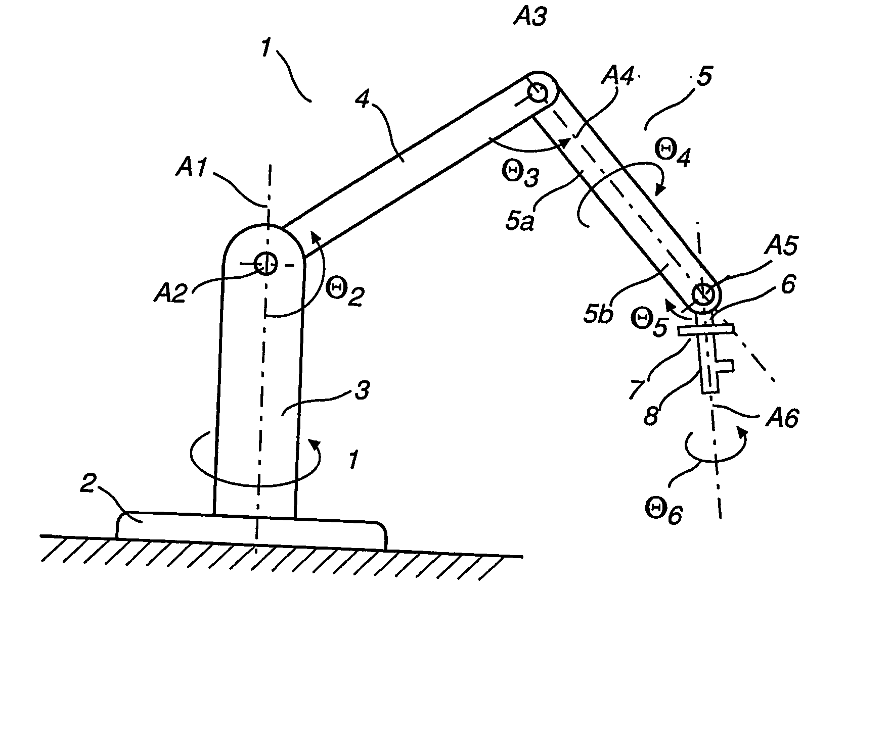
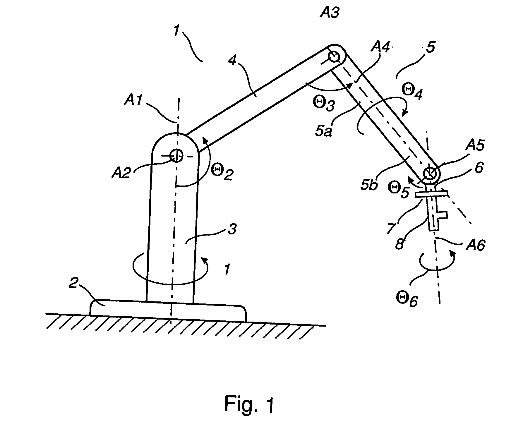
[0029] An industrial robot 1 according the invention contains a stationary foot 2 which carries a stand 3 rotatably arranged around a first axis A1. The stand carries a first robot arm 4 rotatably arranged around a second axis A2. The first arm carries a second robot arm 5 rotatably arranged around a third axis A3. The second arm 5 comprises an inner arm part 5a and an outer arm part 5b. The inner arm part carries the outer arm part, which is rotatably arranged around a forth axis A4, which is coaxial with the longitudinal axis of the inner arm part. The outer arm part carries a wrist part 6 rotatably arranged around a fifth axis A5. The wrist part carries a hand part or a rotating disc 7, which is rotatably arranged around a sixth axis A6. Finally the rotating disc carries a tool 8 for operation by the robot.

[0030]

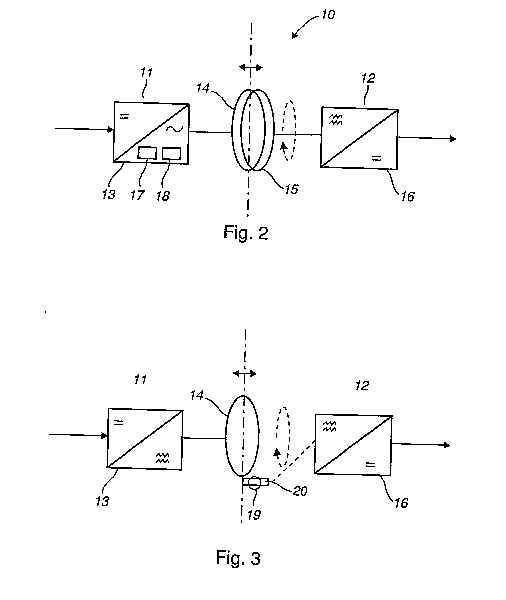
[0031] The power supply system 10 according to FIG. 2 comprises a first part 11 and a second part 12. The first part is attached to the industrial robot 1 and the second...


PUM


Abstract

A power supply system for an industrial robot. The power supply includes a transmitting part including a first coil and a first converter for producing an alternating magnetic field from the first coil. The power supply also includes a receiving part including a second coil for providing an alternating current by induction from the alternating magnetic field and a second converter for producing from the alternating current a direct current for providing power to a tool carried by the robot.

Description

TECHNICAL FIELD [0001] The present invention concerns an industrial robot. More precisely the invention concerns a system for wireless transfer of electric power between a robot and a tool carried by the robot. Preferably the power transferred is in the region up to 5 W. Especially the invention comprises a power supply system for efficient power supply of such a tool comprising the use of air cored coils. BACKGROUND OF THE INVENTION [0002] There are a whole lot of types of tools for robot operations. Some of them are simple and need only compressed air to operate. Others have a more complicated structure an need process media, such as compressed air, cooling media, electric power as well as control signaling between the robot control unit and the tool. Normally all these media, power and control wiring are collected in one process cabling which may be bundled in a flexible tube. In a known arrangement this cabling is arranged on the outside of the robot following the robot arms to ...

Claims


Application Information

Patent Timeline
IPC IPC(8): H02J17/00B25J19/00H02J5/00
CPCH02J5/005B25J19/0029H02J50/402H02J50/12
Inventor SCHEIBLE, GUNTRAMDILGER, BERTHOLDLUTHARDT, COLIN
Owner SCHEIBLE GUNSTREETCAR
Features
  • Generate Ideas
  • Intellectual Property
  • Life Sciences
  • Materials
  • Tech Scout
  • Unparalleled Data Quality
  • Higher Quality Content
  • 60% Fewer Hallucinations
Learn More