Electro-Magnetic Force Driving Actuator and Circuit Breaker Using the Same

a technology of electromagnetic force and actuator, applied in the direction of circuit-breaking switches, superconducting magnets/coils, magnetic bodies, etc., can solve the problems of not operating, hydraulic or pneumatic actuators have a disadvantage of operating fluid leakage according to a change of surrounding, and about 13 of the total cost of circuit breaker, etc., to maximize actuation speed and force, excellent breaking performance, and small size and weigh

Inactive Publication Date: 2007-11-29
EMATECH INC KOREA ELECTRICAL ENG & SCI RES INST
View PDF2 Cites 19 Cited by
  • Summary
  • Abstract
  • Description
  • Claims
  • Application Information

AI Technical Summary

Benefits of technology

[0024] Accordingly, the present invention has been made to solve the above-mentioned problems occurring in the prior art. The object of the present invention is to provide an actuator using an electromagnetic force capable of maximizing actuating speed and forc

Problems solved by technology

However, such actuators make up about ⅓ of the total cost of the circuit breaker and Korea industries mostly depends on the imports thereof.
In addition, the hydraulic or pneumatic actuator has a disadvantage of a leakage of an operating fluid according to a change of surrounding temperature.
Further, since the actuator consists of many parts, it may not operate even when only one part is out of order.
However, since an elastic force of the spring is not constant, a reliability of the operation is low.
Accordingly, it is difficult to apply the spring actuator for the high or super-high pressure circuit breaker which should eject the arc-extinguishing gas, and a possibility of the breaking failure is very high even though it is applied.
However, it is still expensive and difficult to exert a high force.
Accordingly, al

Method used


Image

  • Electro-Magnetic Force Driving Actuator and Circuit Breaker Using the Same
  • Electro-Magnetic Force Driving Actuator and Circuit Breaker Using the Same
  • Electro-Magnetic Force Driving Actuator and Circuit Breaker Using the Same

Examples


example 1

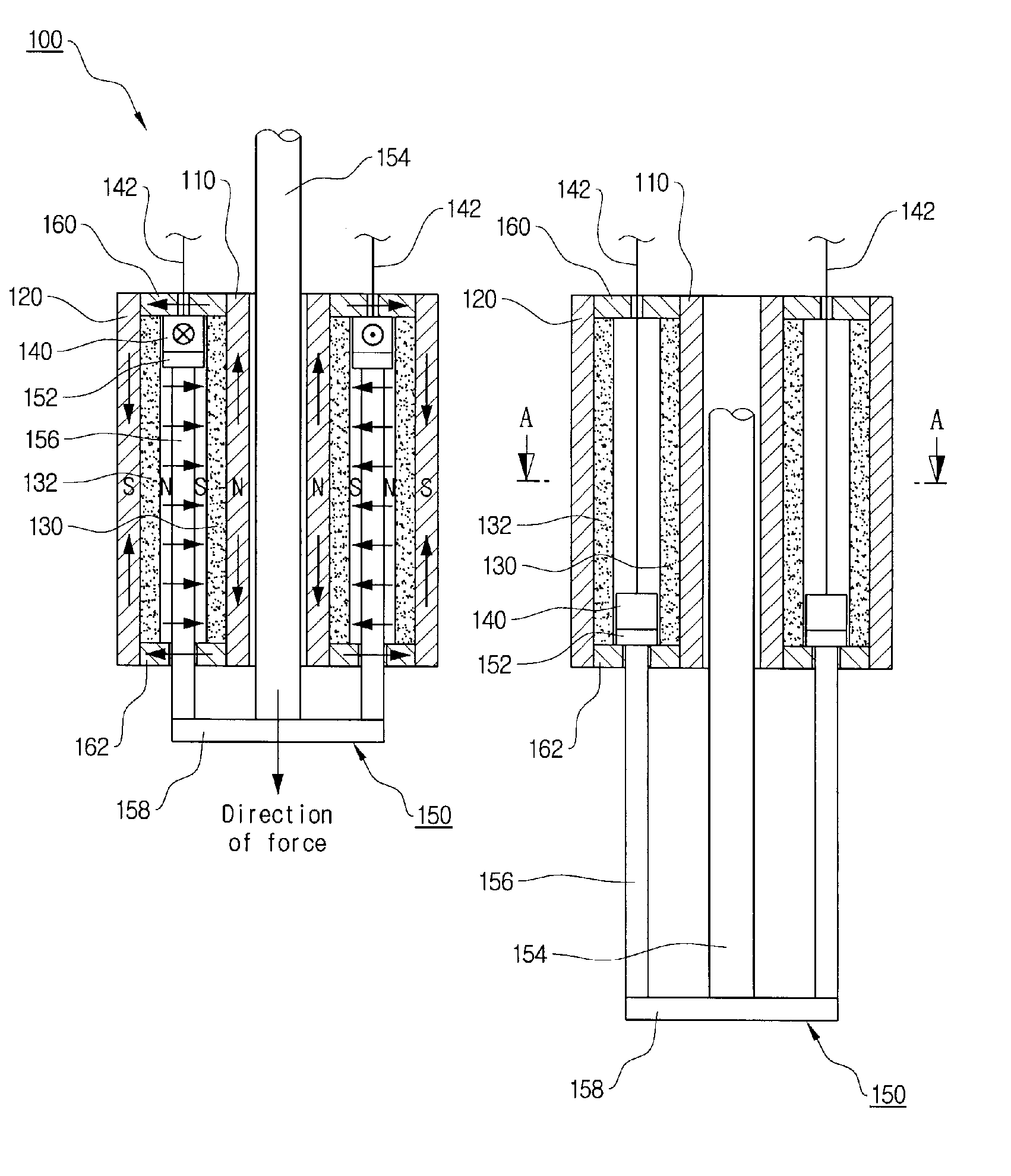
[0065]FIGS. 3 and 4 show an actuator according to a first preferred embodiment of the invention. FIG. 3 is a sectional view showing a structure of the actuator and FIG. 4 is a sectional view taken along a line A-A in FIG. 3.

[0066] In FIG. 3, a right view shows a state before the actuator is operated (i.e., closed state) and a left view shows a state after the actuator is operated (i.e., opened state).

[0067] As shown in FIGS. 3 and 4, the actuator 100 according to the invention is an electro-magnetic force driving actuator (EMFA) and comprises an inner case 110, an outer case 120, inner and outer permanent magnets 130, 132, a coil 140 and a movable member 150.

[0068] The inner and outer cases 110, 120 are made of magnetic material and concentrically positioned to maintain a predetermined radial interval between them.

[0069] The inner permanent magnet 130 is mounted to abut on an outer surface of the inner case 110 and the outer permanent magnet 132 is mounted to abut on an inner su...

example 2

[0106] FIGS. 8 to 10 show an actuator according to a second embodiment of the invention. The actuator according to the second embodiment is a modified form of the electro-magnetic force driving actuator (EMFA) according to the first embodiment of the invention.

[0107] As shown in FIG. 8, the actuator 200 according to the second embodiment comprises a magnetic body 210 having a circular chamber 211 formed therein, a circular inner permanent magnet 220 and a circular outer permanent magnet 230 concentrically mounted to maintain a predetermined radial interval between them in the chamber 211 of the body 210, and a circular movable member 240 having a circular coil 241 and mounted to be linearly movable in an axial direction between the inner and outer permanent magnets 220, 230.

[0108] The movable member 240 having the coil 241 is linearly moved in the axial direction between the inner and outer permanent magnets 220, 230 with forces occurring due to magnetic fields by the inner and ou...

example 3

[0136]FIGS. 20 and 21 show an electromagnetic force driving actuator 300 according to a third embodiment of the invention. The actuator 300 according to the third embodiment is such that a plurality of the actuators 200 (four in Figs.) according to the second embodiment are mounted to one body 310. In other words, a plurality of actuating parts 300a, 300b, 300c, 300d may be mounted to the body 310 made of magnetic material. Each of the actuating parts 300a, 300b, 300c, 300d comprises the inner and outer permanent magnets 220, 230, the movable member 240 having the coil and the first and second magnetic rings, the first and second inner and outer supplementary permanent magnets 251, 252 and 255, 256 and the first and second buffering means 261, 262, likewise the actuator according to the second embodiment. Each of the movable members 240 is connected with the plurality of rods 271, 272 which are connected to supporting members 321, 322. The upper supporting member 321 is provided wit...


PUM


Abstract

Disclosed are an electro-magnetic force driving actuator and a circuit breaker comprising the actuator. The actuator comprises a hollow inner case made of magnetic material; an outer case made of magnetic material and being concentric with the inner case and radially mounted at an interval outwardly from the inner case; inner and outer permanent magnets abutting on an outer surface of the inner case and an inner surface of the outer case, respectively and positioned to maintain a predetermined gap between the magnets; a coil mounted to be linearly movable in an axial direction between the inner and outer permanent magnets; and a non-magnetic movable member having an end to which the coil is provided and linearly moving in the axial direction between the inner and outer permanent magnets with electromagnetic repulsive forces occurring due to magnetic fields by the inner and outer permanent magnets and a current density of the coil when current is supplied to the coil. The circuit breaker comprises the actuator and an insulation-actuating rod connected to another end of the movable member and linearly moving by the movable member to perform closing and opening operations.

Description

TECHNICAL FIELD [0001] The present invention relates to an actuator and a circuit breaker used to an electric power system, and more particularly to an actuator using an electromagnetic repulsive force capable of maximizing actuating speed and force while having small size and weight and a circuit breaker usefully applied for high pressure and super-high pressure circuit breakers by exhibiting an excellent circuit-breaking performance using the actuator and also easily applied for a low pressure circuit breaker. BACKGROUND ART [0002] A circuit breaker is mainly mounted to a power transmission end and a power receiving end of a power transmission line. The breaker opens and closes a normal current when there is no failure in an electric power system and also breaks a fault current when there occurs a failure such as a circuit short, thereby protecting the system and various power devices (load). [0003] The circuit breaker is classified into a vacuum circuit breaker (VCB), an oil circ...

Claims


Application Information

Patent Timeline
IPC IPC(8): H01H83/00H01F6/00H01H33/38
CPCH01H33/38H01F7/066
Inventor KANG, JONG-HOJEONG, HYUN-KYO
Owner EMATECH INC KOREA ELECTRICAL ENG & SCI RES INST
Why Eureka
Try Eureka