Quick Release Connector That Is Assembled Easily And Quickly

Inactive Publication Date: 2007-11-29
CHENG SHIH CHUNG
View PDF8 Cites 15 Cited by
  • Summary
  • Abstract
  • Description
  • Claims
  • Application Information

AI Technical Summary

Benefits of technology

[0008]The primary objective of the present invention is to provide a quick release connector that is assembled easily and quickly.
[0009]Another objective of the present invention is to provide a quick release connector, wherein the locking blocks are combined together by limit of the positioning ring, so that the locking blocks of the positioning ring are placed into the receiving holes and the guide slots of the connector body easily and quickly, thereby simplifying the construction of the quick release connector, and thereby facilitating assembly and fabrication of the quick release connector.
[0010]A further objective of the present invention is to provide a quick release connector, wherein the catch walls are formed on tw

Problems solved by technology

However, it is necessary to place all of the locking blocks 60 into the receiving holes 51 of the connector body 50, so that the quick release connector cannot be assembled easily and quickly, thereby wasting time and increasing costs of assembly and fabrication of the quick release

Method used


Image

  • Quick Release Connector That Is Assembled Easily And Quickly
  • Quick Release Connector That Is Assembled Easily And Quickly
  • Quick Release Connector That Is Assembled Easily And Quickly

Examples


Example

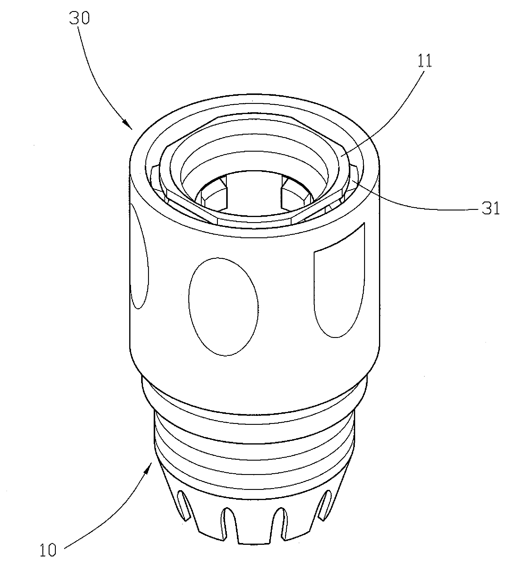
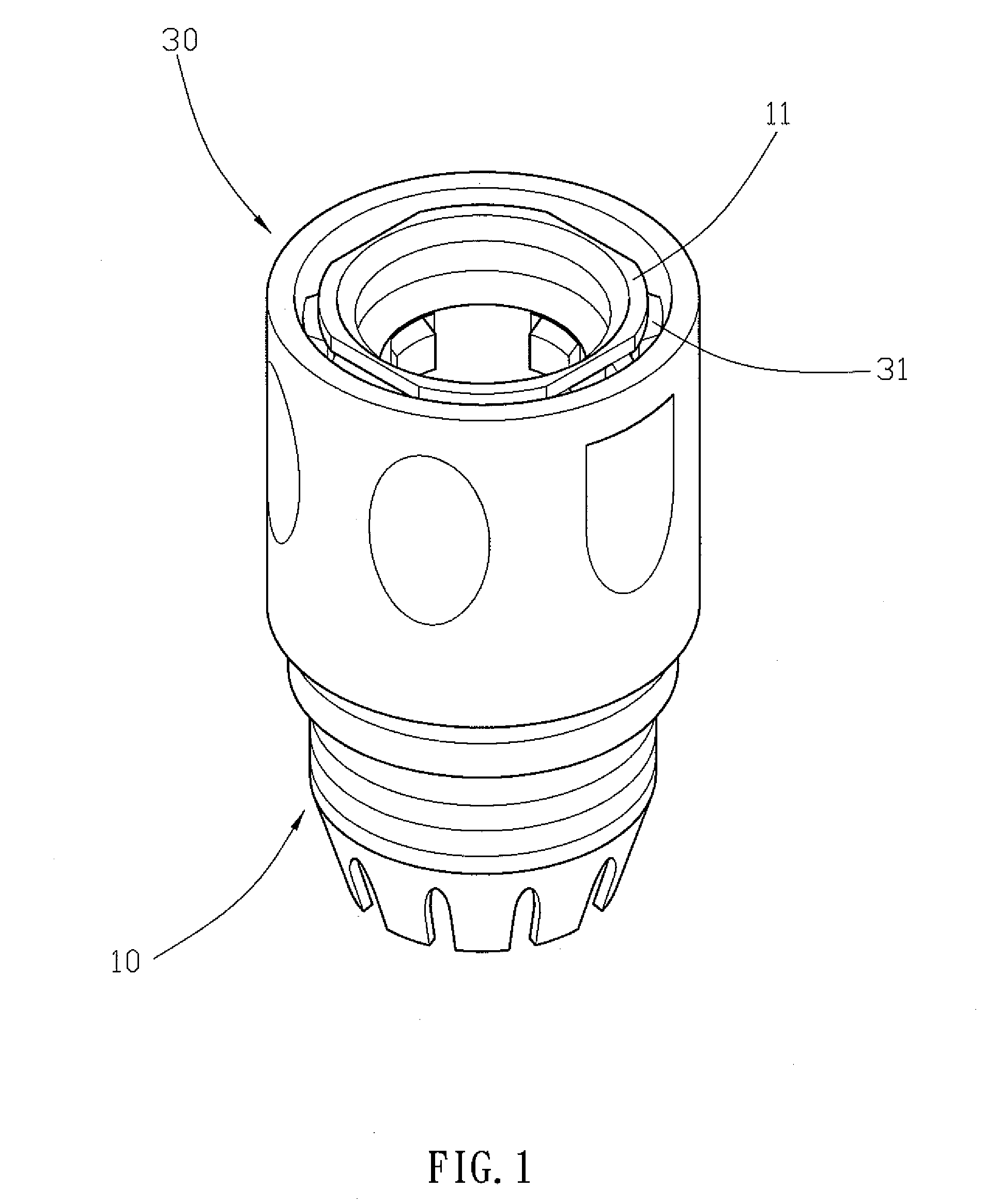
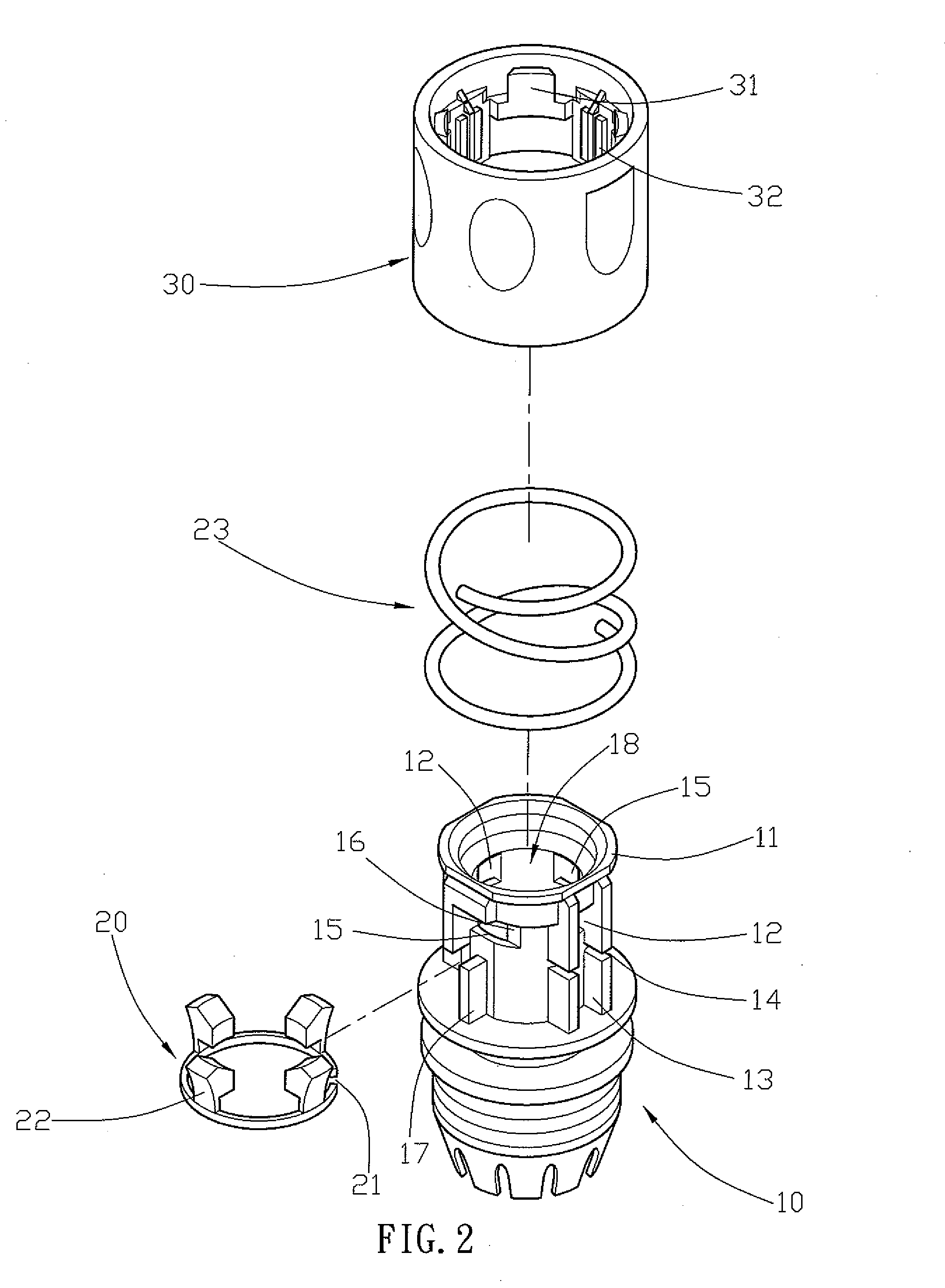
[0021]Referring to the drawings and initially to FIGS. 1-3, a quick release connector in accordance with the preferred embodiment of the present invention comprises a connector body 10 having an inside formed with a mounting chamber 18 and having a peripheral wall formed with two opposite receiving holes 12 connected to the mounting chamber 18 and two opposite guide slots 15 connected to the mounting chamber 18, a positioning ring 20 mounted on the peripheral wall of the connector body 10 and provided with a plurality of flexible locking blocks 22 movably mounted in the receiving holes 12 and the guide slots 15 of the connector body 10 and extendable into the mounting chamber 18 of the connector body 10, a mounting sleeve 30 movably mounted on the connector body 10 and having an inner wall provided with a plurality of inwardly extending push blocks 32 that are movable to press the locking blocks 22 of the positioning ring 20 to push the locking blocks 22 of the positioning ring 20 i...


PUM


Abstract

A quick release connector includes a connector body, a positioning ring, a mounting sleeve, and an elastic member. The connector body has a peripheral wall formed with two opposite receiving holes and two opposite s guide slots. The positioning ring is provided with a plurality of flexible locking blocks. Thus, the locking blocks are combined together by the positioning ring, so that the locking blocks of the positioning ring are placed into the receiving holes and the guide slots of the connector body easily and quickly, thereby simplifying the construction of the quick release connector, and thereby facilitating assembly and fabrication of the quick release connector.

Description

BACKGROUND OF THE INVENTION[0001]1. Field of the Invention[0002]The present invention relates to a connector and, more particularly, to a quick release connector.[0003]2. Description of the Related Art[0004]A conventional quick release connector in accordance with the prior art shown in FIGS. 6-8 comprises a connector body 50 having an inside formed with a mounting chamber 58 and having a peripheral wall formed with four receiving holes 51 connected to the mounting chamber 58, four locking blocks 60 movably mounted in the receiving holes 51 of the connector body 50 and extendable into the mounting chamber 58 of the connector body 50, a mounting sleeve 70 movably mounted on the connector body 50 and having an inner wall provided with a plurality of push blocks 72 that are movable to push the locking blocks 60 into the mounting chamber 58 of the connector body 50, and an elastic member 61 mounted on the connector body 50 and biased between the connector body 50 and the mounting sleeve...

Claims


Application Information

Patent Timeline
IPC IPC(8): H01R4/24
CPCF16L37/0982F16L37/086
Inventor CHENG, SHIH-CHUNG
Owner CHENG SHIH CHUNG
Why Eureka
Try Eureka