Method for Selecting Aircraft Access Point into a Lateral Free Eveolution Area

a technology of aircraft access point and lateral free eveolution area, which is applied in the direction of navigation instruments, instruments, energy saving arrangements, etc., can solve the problems of not being able to adjust sensitivity and avoidance trajectory simplest to implemen

Active Publication Date: 2007-11-29
THALES SA
View PDF22 Cites 52 Cited by
  • Summary
  • Abstract
  • Description
  • Claims
  • Application Information

AI Technical Summary

Benefits of technology

[0015] Briefly stated, the present invention is directed to a method based on a minimum cost criterion, for the selection by an aircraft, of a point of access to a zone of free lateral deployment, noteworthy in

Problems solved by technology

They pose a problem of adjustment of sensitivity, a compromise having to be sought between timely triggering with each true risk of co

Method used


Image

  • Method for Selecting Aircraft Access Point into a Lateral Free Eveolution Area
  • Method for Selecting Aircraft Access Point into a Lateral Free Eveolution Area
  • Method for Selecting Aircraft Access Point into a Lateral Free Eveolution Area

Examples


Embodiment Construction

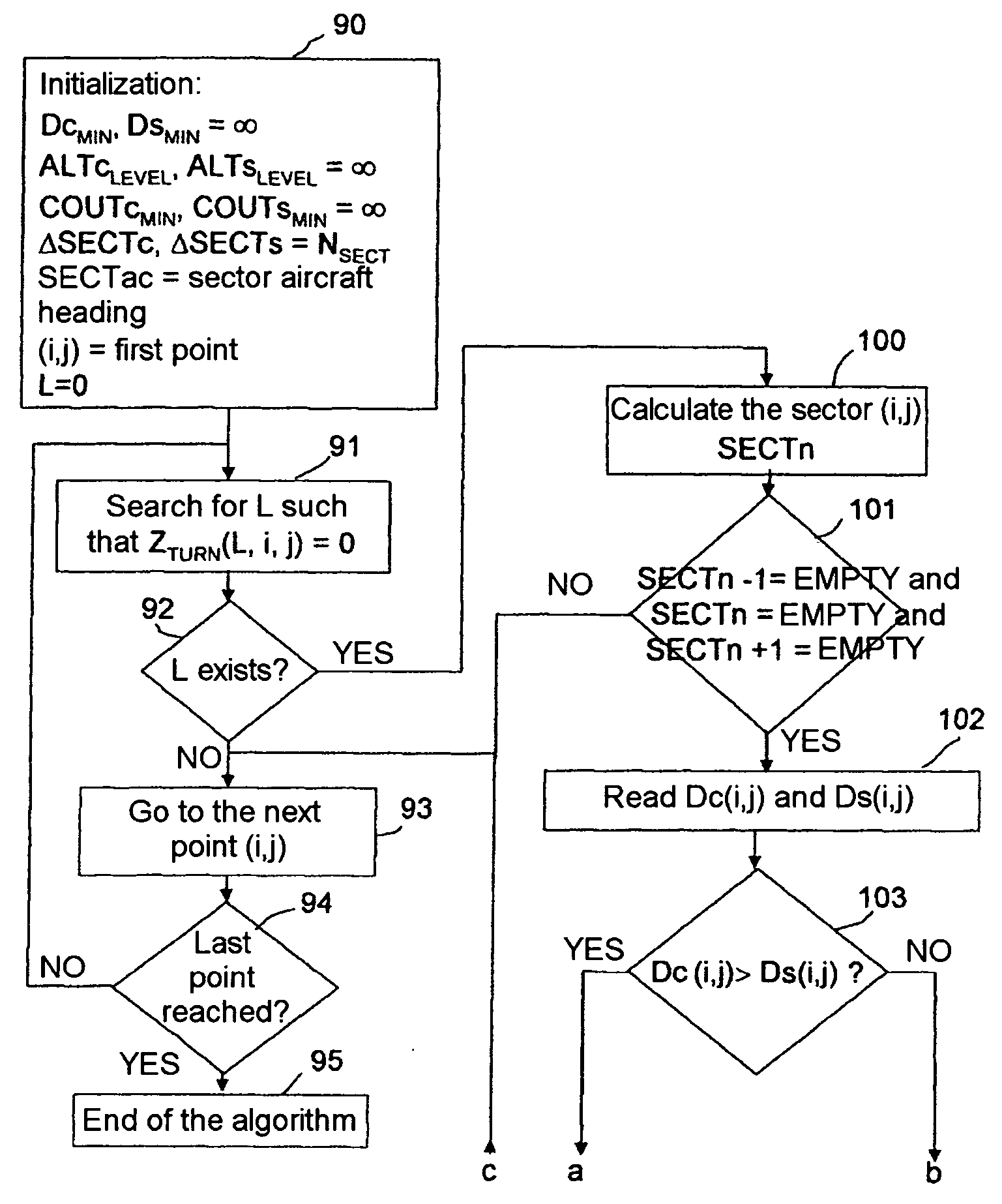
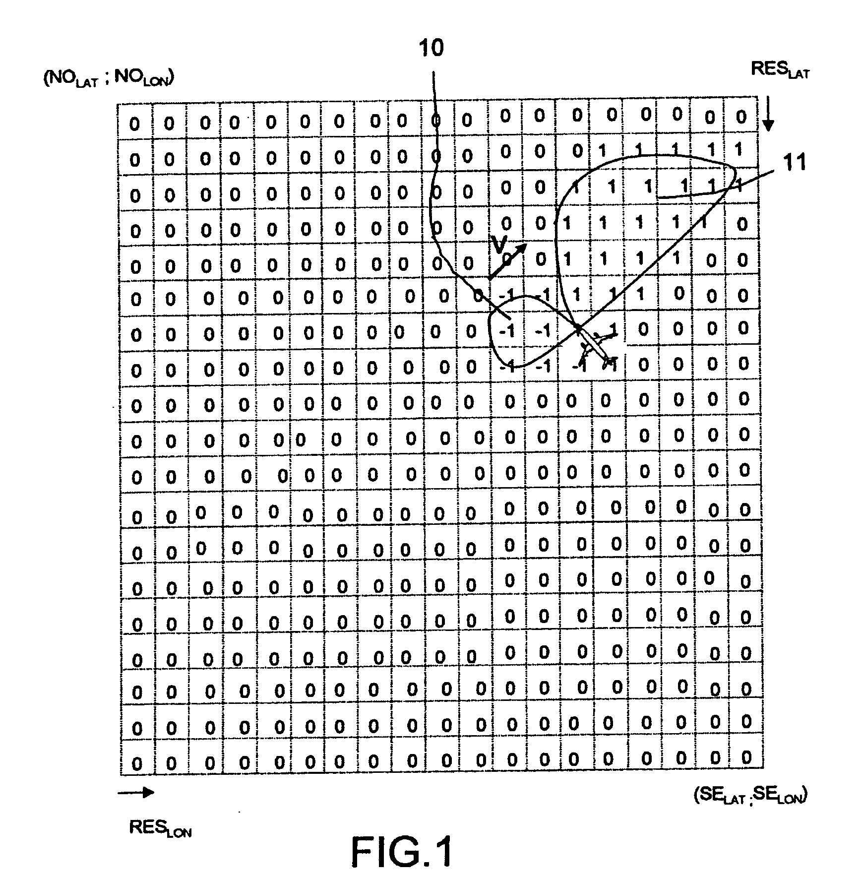
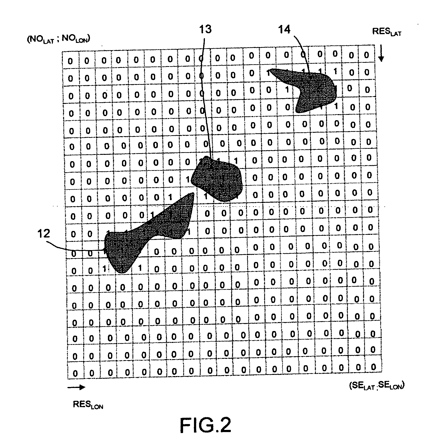
[0083] A procedure for searching for zones of free lateral deployment in the airspace where the aircraft is deploying and for selecting in a tagged zone of free lateral deployment, entry points that are optimal from the point of view of the joining trajectory will be described hereinbelow. To facilitate comprehension, the description of this procedure will be structured into three main parts: a first part of location and of delimitation of zones of free lateral deployment in the airspace where the aircraft is deploying, a second part of evaluation of the situation of the aircraft in its environment and a third part of identification and of selection of points of entry of zone of free lateral deployment that are the most easily accessible from the current position of the aircraft. It goes without saying that this does not imply that the order of the operations that is adopted for the description has to be rigorously complied with in a real implementation.

[0084] The first part of loc...


PUM


Abstract

This method facilitates the joining, by an aircraft, of a secure zone, without constraint of deployment in the horizontal plane, in particular when the latter is threatened by a risk of collision with the ground or by a risk of penetration into a forbidden zone which cannot be resolved by a purely vertical avoidance maneuver. It consists in selecting a point for joining a zone of free lateral deployment by means of a criterion of minimum cost of the initial maneuver of turning at the start of the trajectory for joining the possible points of access to the zones of free lateral deployment.

Description

CROSS-REFERENCE TO RELATED APPLICATIONS [0001] The present Application is based on International Application No. PCT / EP2005 / 051312, filed on Mar. 22, 2005, which in turn corresponds to France Application No. 04 / 03769 filed on Apr. 9, 2004, and priority is hereby claimed under 35 USC §119 based on these applications. Each of these applications are hereby incorporated by reference in their entirety into the present application. [0002] This application is related to U.S. application Ser. No. 10 / 519,100 filed on Jun. 27, 2003; U.S. application Ser. No. 10 / 573,410 filed on Sep. 8, 2004; U.S. application Ser. No. 10 / 577,063 filed on Oct. 21, 2004; U.S. application Ser. No. 10 / 583,144 filed on Nov. 30, 2004; and U.S. application Ser. No. 10 / 590,083 filed on Feb. 8, 2005.BACKGROUND OF THE INVENTION [0003] 1. Field of the Invention [0004] The present invention relates to methods for the joining, by an aircraft, of a secure zone, with a minimum of constraint in the horizontal plane. It deals ...

Claims


Application Information

Patent Timeline
IPC IPC(8): G01C21/00G06F17/00G01S13/935G05D1/02G08G5/04
CPCG01C21/005G01S13/94G05D1/0005G08G5/045G08G5/0086G01S13/935
Inventor BITAR, ELIASMARTY, NICOLAS
Owner THALES SA
Why Eureka
Try Eureka