
Hoisting device with a catch nut

Inactive Publication Date: 2007-12-06
SEFAC
View PDF12 Cites 8 Cited by
  • Summary
  • Abstract
  • Description
  • Claims
  • Application Information

AI Technical Summary

Benefits of technology

[0017]The aim of the invention is to cope with the drawbacks of the state of the art by providing an economic, fully mechanical solution, which also allows preventing the possible failure due to wear of the most exposed component. This solution also allows equipping existing installations and making them safe, at low cost and without requiring a long immobilization.

Problems solved by technology

The safety of the lifting stands, in particular for motor or railway vehicles, is an important problem, for which different solutions have been provided.
The use of such low-efficiency nuts, subjected to high frictions and significant wear, requires a lubrication installation, as well as high driving power, which results into a high cost.
However, such systems require being themselves double, because the safety system is sensitive to the slightest failure of a circuit or a connection.
This reliable solution requires however a power consumption during the control to cause the load to move upwards.
No means allows preventing the bearing nut from breaking.
The known solutions of the state of the art provide safety in the event of breaking, but they are not designed to cope with and visualize the wear of the bearing nut.
Though they allow an immobilization of the hoisting device in the event of breaking of nut, they are ill-adapted for depositing the lifted load on the floor.

Method used


Image

  • Hoisting device with a catch nut
  • Hoisting device with a catch nut

Examples


Embodiment Construction

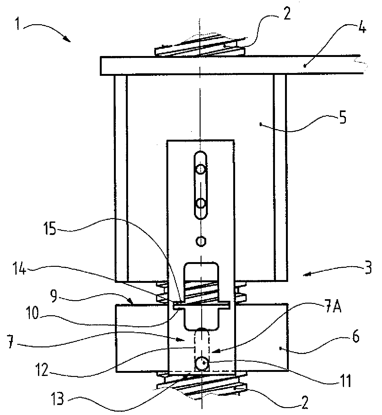
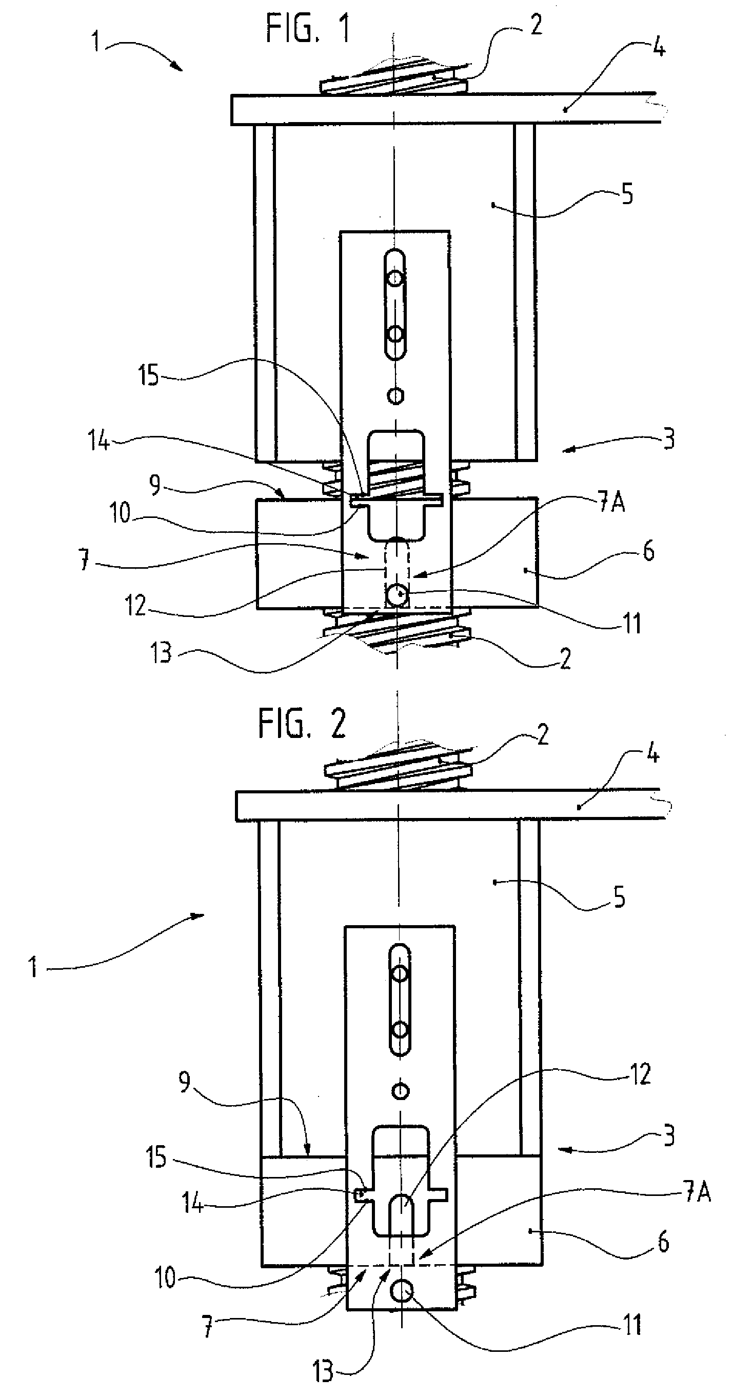
[0025]The invention relates to a hoisting device 1, namely designed for lifting vehicles.

[0026]Such a device 1 includes a substantially vertical column forming a frame.

[0027]It also includes lifting means, which are movable alongside this column under the action of the control, by adequate driving means, to cause a threaded rod 2 to be rotated a and a nut 3 to be moved along the latter.

[0028]On this nut 3 rests, or is mounted integral with, a carriage 4 on which rests a load 20 to be lifted, not shown in the figures.

[0029]It will be understood that a hoisting device comprised of the juxtaposition of several devices as described, namely with, in a traditional way, an even number of columns, falls within the spirit of the invention, and that the present description is limited to only one column only for reasons of simplification.

[0030]The nut 3 is a catch nut. It is comprised of several elements, which are designed capable of cooperating with each other, in certain fields of applicati...


PUM


Abstract

The invention relates to a hoisting device (1), in particular for a vehicle, including a substantially vertical column forming a frame and lifting means movable along said column under the action of the control, by adequate driving means, to cause a threaded rod (2) to rotate and a nut (3) integral with a carriage (4) bearing the load (20) to be lifted to move along the latter.It is characterized in that this nut (3) is a catch nut, which comprises a first bearing nut (5) on which said carriage (4) rests, and a second safety nut (6) coaxial to the preceding one and placed below same, designed capable of receiving and bearing the load formed by said carriage (4) and its load (20) and by said first bearing nut (5) in the event of failure of the latter.

Description

BACKGROUND OF THE INVENTION[0001](1) Field of the Invention[0002]The present invention relates to a hoisting device, in particular for a vehicle, including a substantially vertical column forming a frame and lifting means movable alongside said column under the action of the control, by adequate driving means, to cause a threaded rod to rotate and a nut integral with a carriage on which rests the load to be lifted to move along the latter.[0003]The present invention will find its application in the field of the handling devices and, in particular, of the hoisting devices in particular for vehicles.[0004](2) Description of the Prior Art[0005]The safety of the lifting stands, in particular for motor or railway vehicles, is an important problem, for which different solutions have been provided.[0006]Many hoisting devices are in the form of a vertical column forming a frame, or of a plurality of such columns, resting on the floor through a base plate. Along such a vertical column are ca...

Claims


Application Information

Patent Timeline
IPC IPC(8): B66F3/08
CPCB66F7/14F16H25/2472B66F7/28
Inventor LETELLIER, ERIC
Owner SEFAC
Learn More