Apparatus and method for a current limiting bleeder device shared by columns of different memory arrays

Active Publication Date: 2005-08-23
MICRON TECH INC
View PDF12 Cites 6 Cited by
  • Summary
  • Abstract
  • Description
  • Claims
  • Application Information

AI Technical Summary

Benefits of technology

[0008]The present invention is directed to a memory device having a current limiting bleeder device that is shared between columns of different memory arrays that limits a current load on a voltage supply to prevent failure of an otherwise repairable device. The memory device includes first and second memory arrays having memory cells arranged in rows and columns. Each of the columns of the first and second memory arrays is coupled to an equilibration circuit to precharge the columns. Further included in the memory device is a bleeder device coupled to a precharge voltage supply and further cou

Problems solved by technology

For example, a well known failure mode occurs when a digit line is short circuited to a word line.
Additionally, the additional load on the word line that is short circuited to the digit line may be such that the word line cannot achieve a sufficient voltage level in the region of the short circuit to couple the memory cells to the respective digit line.
As a result, the memory cells of the shorted row in the vicinity of the short circuit are also defective.
The defective column and row results in a failure pattern that produces a “cross” of defective memory cells.
Having a sufficient amount of redundant memory, however, does not ensure that a memory device having cross failures can operate normally.
Although the defective columns and rows of memory can be replaced with redundant rows and columns of memory

Method used


Image

  • Apparatus and method for a current limiting bleeder device shared by columns of different memory arrays
  • Apparatus and method for a current limiting bleeder device shared by columns of different memory arrays
  • Apparatus and method for a current limiting bleeder device shared by columns of different memory arrays

Examples


Example

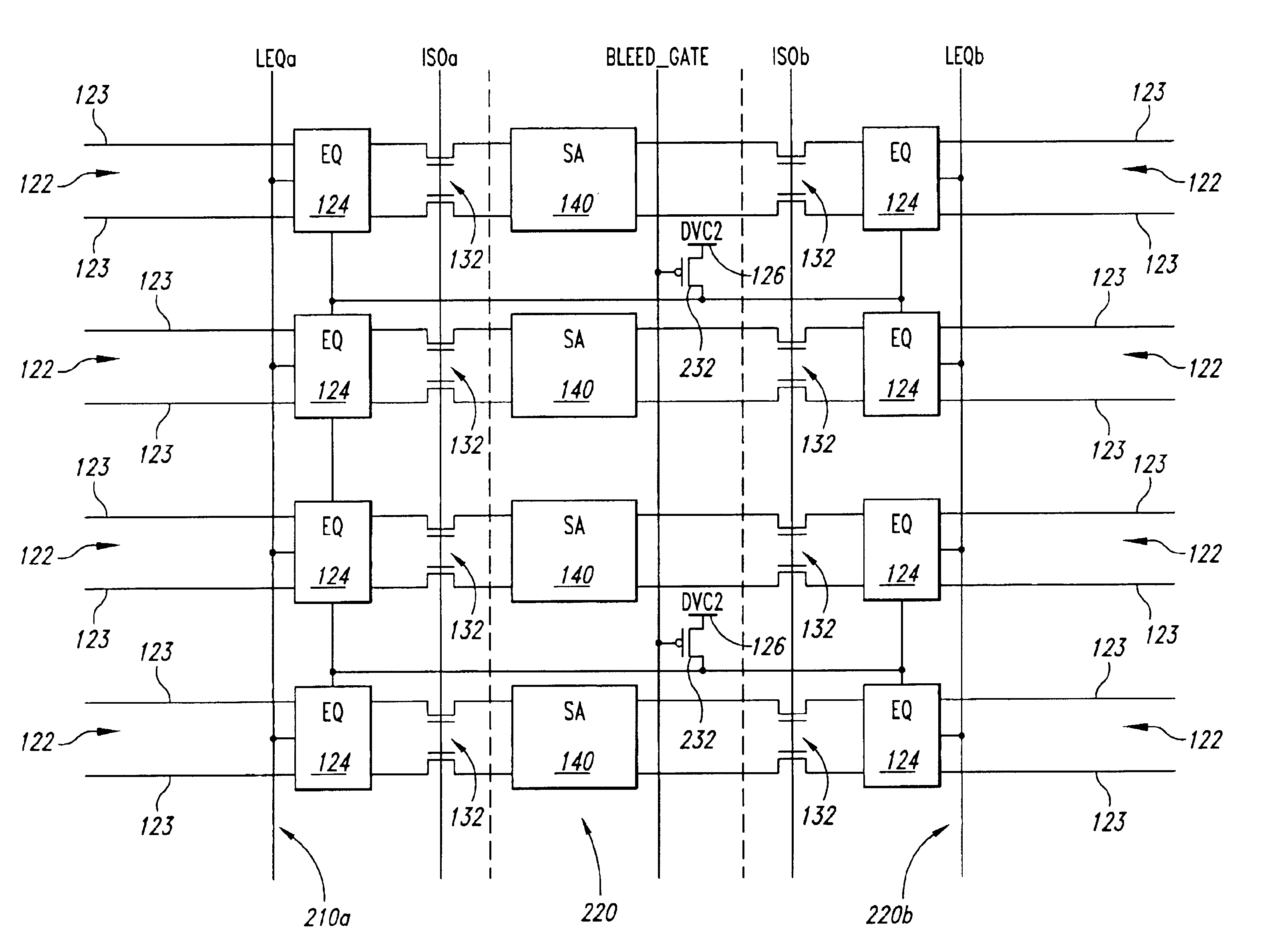
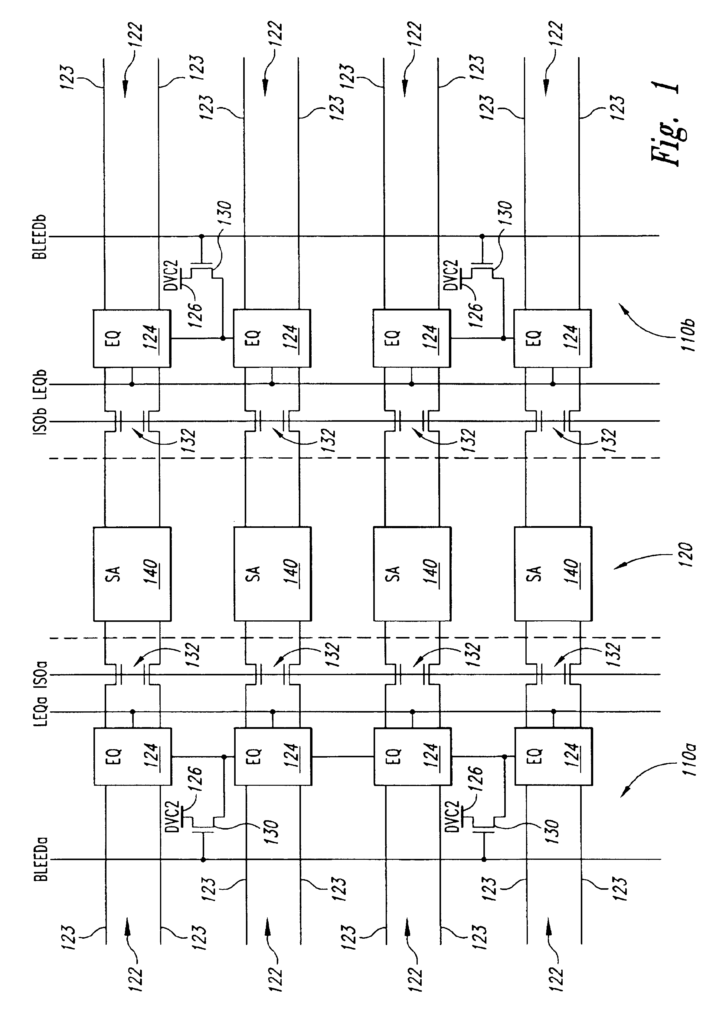
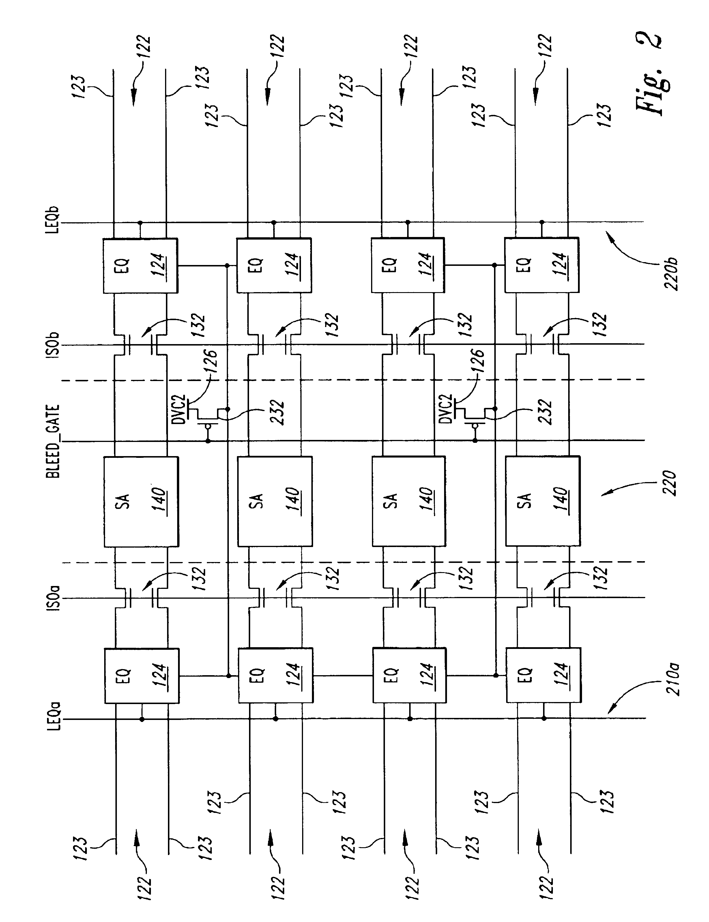
[0012]Embodiments of the present invention are directed to memory device having a current limiting bleeder device shared between columns of different memory arrays for limiting the current load on a voltage supply in the event an unusually high current load results from a repairable defect. In the following detailed description of exemplary embodiments of the invention, reference is made to the accompanying drawings, which form a part hereof, and in which are shown, by way of illustration, specific exemplary embodiments in which the invention may be practiced. These embodiments are described in sufficient detail to enable those skilled in the art to practice the invention. However, it will be clear to one skilled in the art that the invention may still be practiced without these particular details. In other instances, well-known circuits, control signals, timing protocols, and software operations have not been shown in detail in order to avoid unnecessarily obscuring the invention. ...


PUM


Abstract

Apparatus and method for a current limiting bleeder device that is shared between columns of different memory arrays and limits a current load on a voltage supply to prevent failure of an otherwise repairable memory device. The memory device includes first and second memory arrays having memory cells arranged in rows and columns where each of the columns of the first and second memory arrays have a equilibration circuit to precharge the respective column. A bleeder device is coupled to a precharge voltage supply and further coupled to at least one equilibration circuit of a column in the first memory array and to at least one equilibration circuit of a column in the second memory array to limit the current drawn by the equilibration circuits from the precharge voltage supply.

Description

TECHNICAL FIELD[0001]The present invention relates generally to the field of computer memories, and more particularly, to an apparatus and method for sharing a current limiting device between columns of different memory arrays, thus, providing flexible layout options for high density DRAM architectures.BACKGROUND OF THE INVENTION[0002]As is generally known, conventional dynamic random access memory (DRAM) devices include memory arrays having memory cells arranged in rows and columns. Each of the memory cells are typically formed from a capacitor, which acts as the storage node, and an access device that couples the capacitor to a sense node at which the charge state of the capacitor is sensed and amplified by a sense amplifier. The sense node is typically represented by a digit line. The digit lines are grouped in complementary pairs that are coupled to a respective sense amplifier. One pair of digit lines represents a column of memory cells. The access devices for a row of memory c...

Claims


Application Information

Patent Timeline
IPC IPC(8): G11C7/00G11C7/12
CPCG11C7/12G11C2207/005
Inventor THOMPSON, J. WAYNERAAD, GEORGE B.KIRSCH, HOWARD C.
Owner MICRON TECH INC
Why Eureka
Try Eureka