Knob

A knob and segment technology, applied in the field of knobs, can solve problems such as affecting the performance of electronic products, cracking or slipping of the clamping end, and eccentricity of the rotary switch, so as to prevent breakage or slippage, prevent slippage or failure, Uniform force effect

Active Publication Date: 2013-06-12
OMRON SHANGHAI
View PDF5 Cites 6 Cited by
  • Summary
  • Abstract
  • Description
  • Claims
  • Application Information

AI Technical Summary

Problems solved by technology

However, there are often certain tolerances in the processing and assembly of electronic products, which will cause the axis line of the rotary switch and the axis line of the knob positioning hole on the panel to be out of line, that is, eccentricity occurs
Therefore, there will be eccentricity between the knob and the rotary switch after assembly
However, the existing knob has no elasticity and is arranged so that the engaging end and the operating end are located on the same axis, so when the tolerance is large, it is easy to cause the breaking of the engaging end or the sliding teeth, etc., thereby Greatly affects the performance of electronic products

Method used


Image

  • Knob
  • Knob
  • Knob

Examples


Embodiment Construction

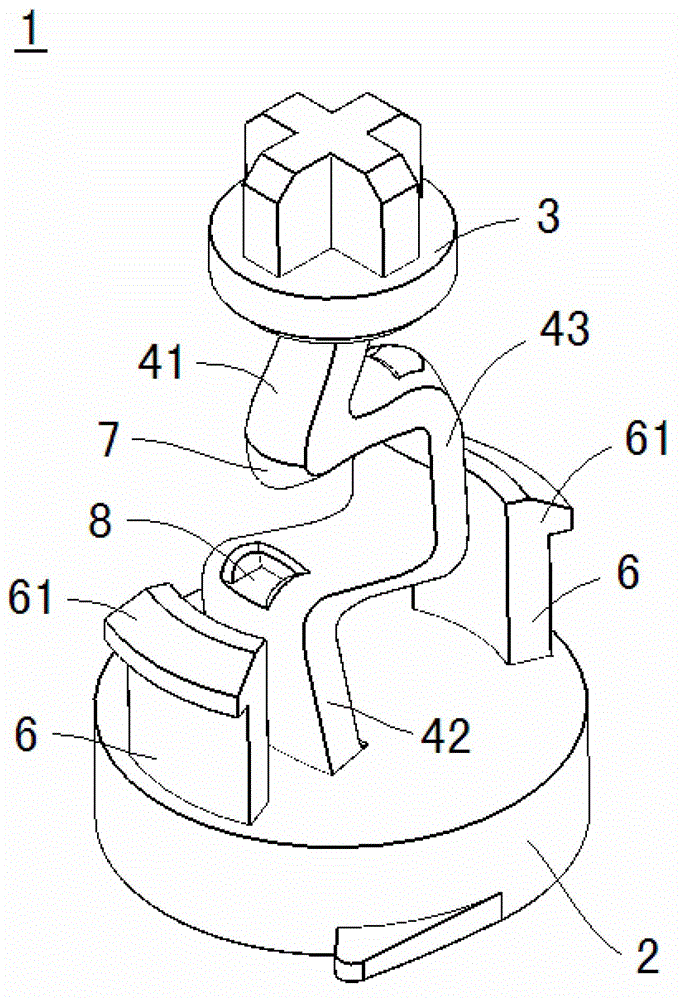
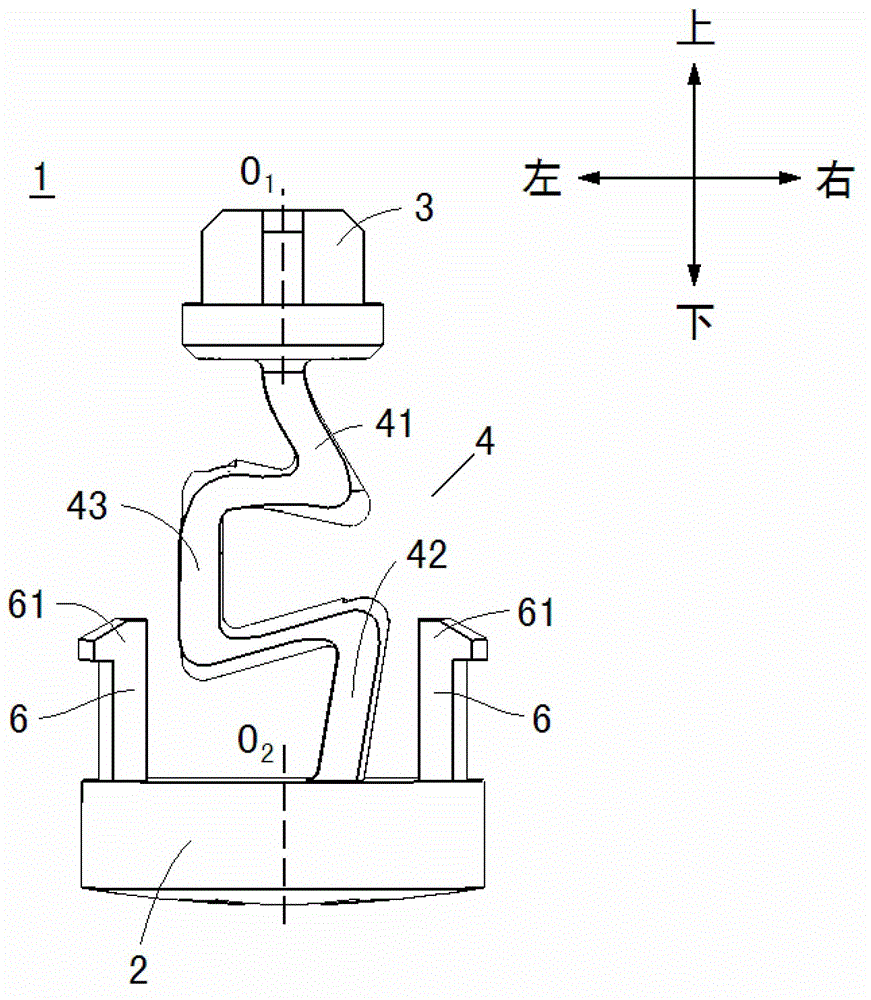
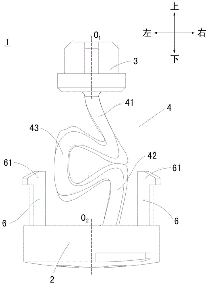
[0020] Below, refer to Figure 1-3 Embodiments of the present invention will be described.

[0021] The knob of the present invention can be used to be installed on the panel of the electronic product. like figure 1 , figure 2 as well as image 3 As shown, the knob 1 has: an operating part 2 at the lower part, an engaging part 3 at the upper part, and a connecting part 4 between the operating part 2 and the engaging part 3 for connecting the operating part 2 and the engaging part 3 .

[0022] The operation member 2 is exposed to the outside of the panel when the knob 1 is attached to the panel. A cross-shaped groove is formed on the surface of the operation part 2 exposed to the outside of the panel, and an operator can insert a tool such as a screwdriver into the groove to rotate the knob 1 . Two locking portions 6 , 6 are formed on the peripheral portion of the upper side of the operation member 2 . The two buckle parts 6 , 6 are arranged opposite to the axis O2 of th...


PUM


Abstract

The invention provides a knob, which is provided with an operating part, a clamping part, and a connecting part with elasticity, wherein the connecting part is provided with a first section part of which one end part is connected with the clamping part, a second section part of which one end part is connected with the operating part, and a third section part of which one end part is connected with the other end part of the first section part and the other end part is connected with the other end part of the second section part; the third section part is curved in a manner that the first section part can be displaced relative to the second section part through deformation of the third section part; a bulge is formed at one connecting part of the connecting part between the third section part and the first section part or the connecting part between the third section part and the second section part, and a groove is formed at the other connecting part; and the bulge can be clamped with the groove. The knob has the advantage that through self-deformation, phenomena such as breakage or screw looseness, even under the condition that a rotary switch is eccentric with a knob positioning hole, of the clamping part can be prevented from occurring.

Description

technical field [0001] The invention relates to a knob for being installed on a panel of an electronic product. Background technique [0002] In electronic products, a knob is installed on the panel, and the engaging end of the knob is formed with a cross protrusion to engage with the cross groove of the rotary switch in the panel. The operating end of the knob is exposed outside the panel, and a cross groove is formed on the outer surface. , for the operator to operate to rotate the knob. However, there are often certain tolerances in the processing and assembly of electronic products, which will cause the axis line of the rotary switch and the axis line of the knob positioning hole on the panel to be out of alignment, that is, eccentricity occurs. Therefore, there will also be an eccentricity between the knob and the rotary switch after assembly. However, the existing knob has no elasticity and is arranged so that the engaging end and the operating end are located on the...

Claims


Application Information

Patent Timeline
Patent Type & Authority Applications(China)
IPC IPC(8): H01H19/14
Inventor 李思引
Owner OMRON SHANGHAI
Why Eureka
Try Eureka