Dc Motor With Supressor

Inactive Publication Date: 2007-12-06
ROBERT BOSCH GMBH
View PDF13 Cites 18 Cited by
  • Summary
  • Abstract
  • Description
  • Claims
  • Application Information

AI Technical Summary

Problems solved by technology

It is disadvantageous, however, that such an arrangement comprises a relatively large number of individual components and in manufacture requires many processing steps, using various connecting proc

Method used


Image

  • Dc Motor With Supressor
  • Dc Motor With Supressor
  • Dc Motor With Supressor

Examples


Embodiment Construction

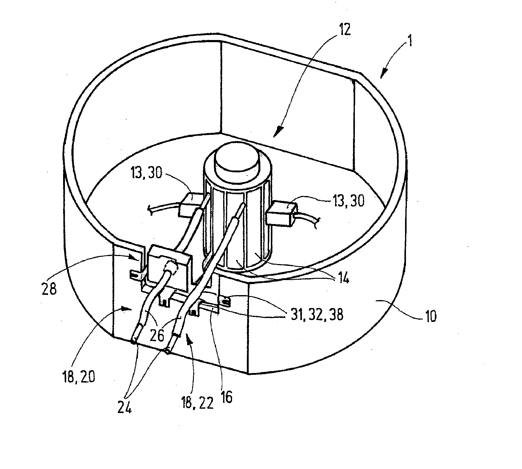
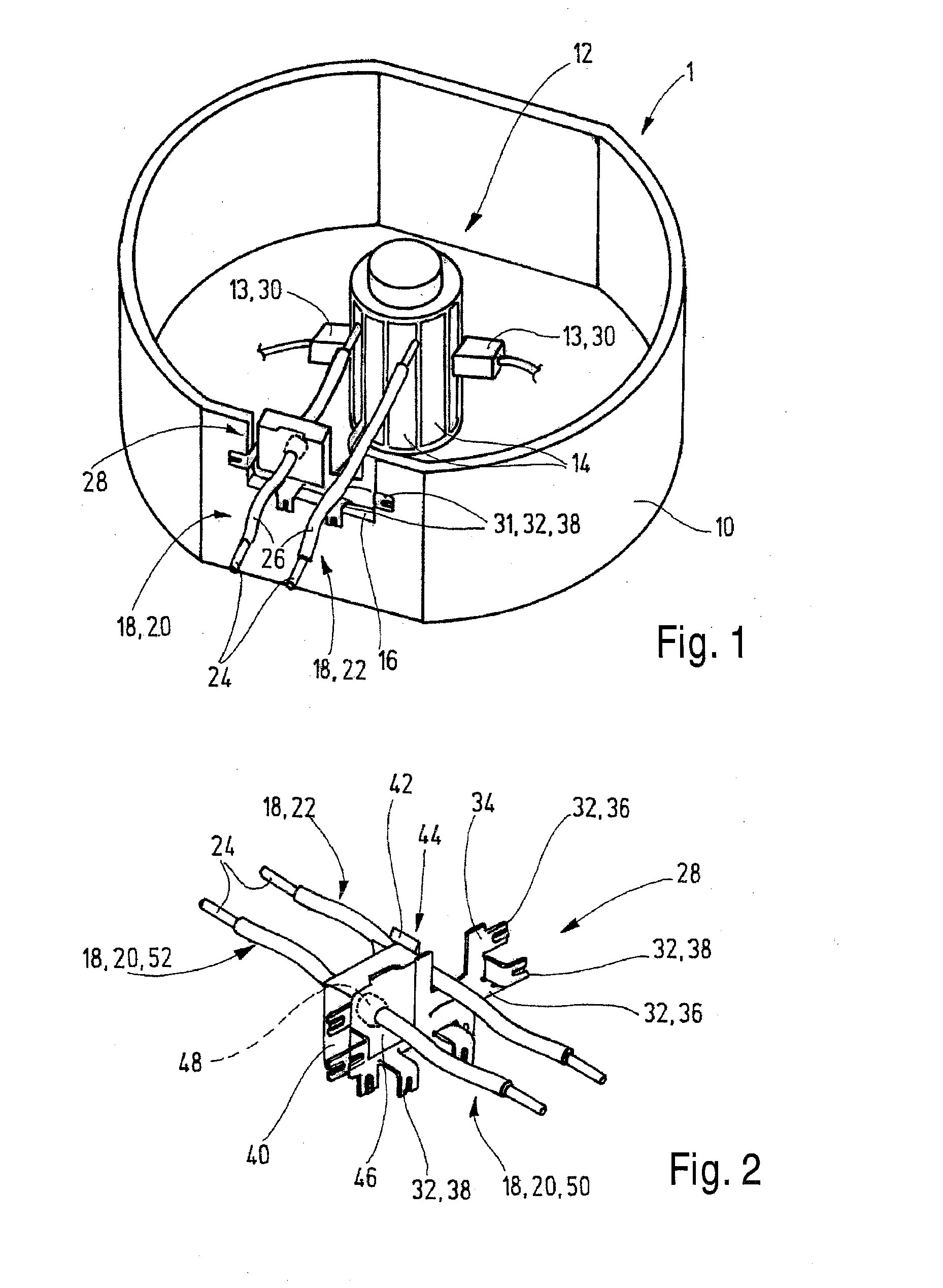
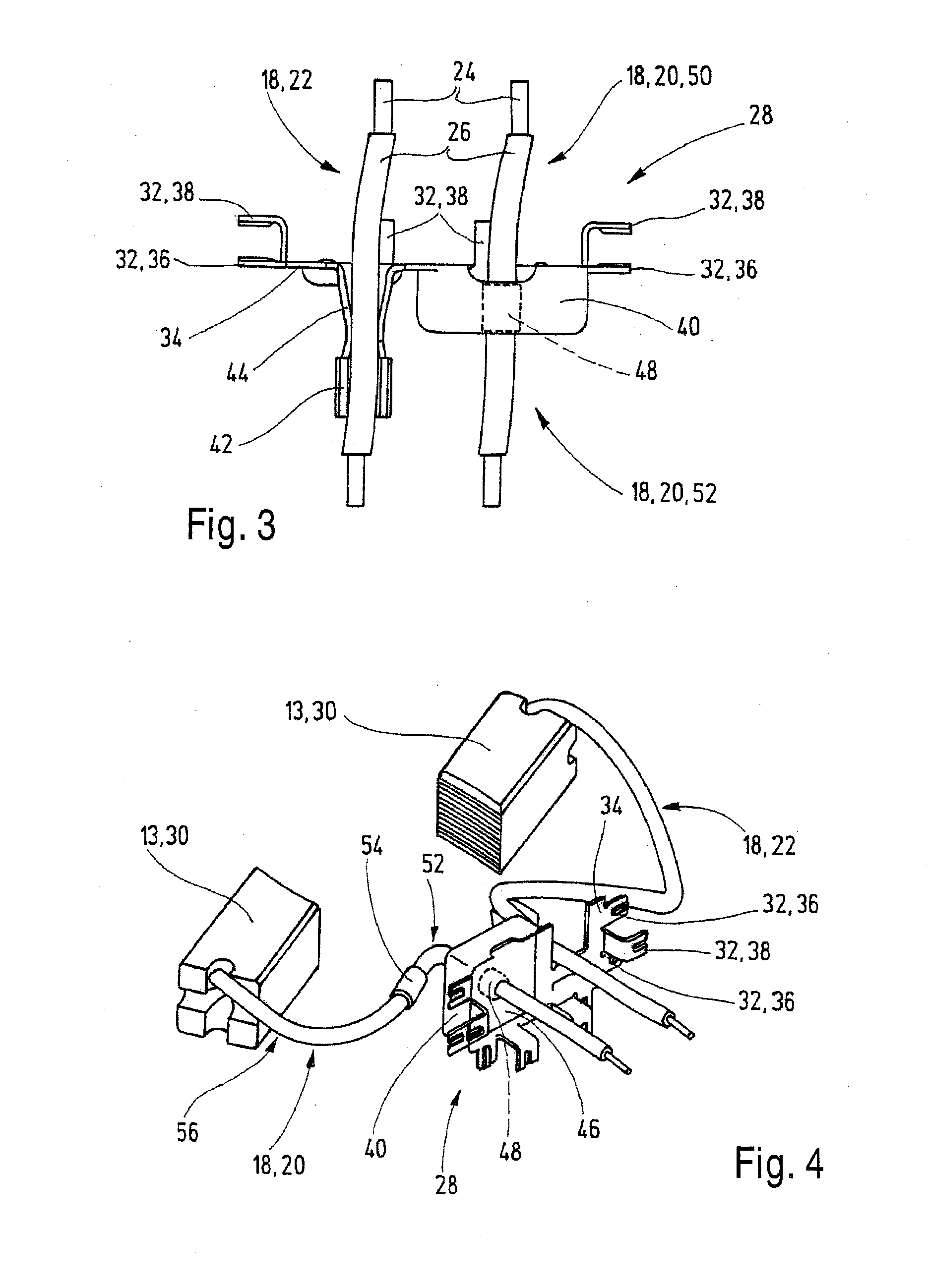
[0026]FIG. 1 shows a DC motor 1; only the elements relevant to the invention have been shown. It should be noted that FIG. 1 is not to scale, and that some components of the DC motor 1, in particular the stator, have not been shown for the sake of greater clarity. The DC motor 1 has the following elements: a pole housing 10, a collector 12 with a plurality of collector laminations 14, two contact elements 13 serving to contact the collector 12 and the collector laminations 14, a pole housing opening 16 for leading through electrical connection lines 18, namely a positive line 20 and a negative line 22, each of the connection lines 18 having a conductor 24 and an insulation 26 surrounding the conductor 24, and an interference suppressor 28 inserted into the pole housing opening 16. The basic mode of operation of a DC motor 1 is well known and will not be further explained here. It should merely be noted that during operation of the DC motor 1, or in other words when the collector 12 ...


PUM


Abstract

A DC motor (1), in particular for a blower device of a motor vehicle, having a pole housing (10), a plurality of contact elements (13) effecting the bonding to a collector (12), a pole housing opening (16) making it possible to feed electrical connection lines (18) through into the pole housing (10), and an interference suppressor (28, 28.1) serving to reduce and/or eliminate line-conducted electrical interference signals, in which the interference suppressor (28, 28.1) has at least one leadthrough capacitor (48), which is located in an electrical path of at least one connection line (18). The invention further relates to an electrical interference suppressor (28, 28.1) for an electrical device located in a housing, in particular for a DC motor (1) in a pole housing (10), as well as to the use of a leadthrough capacitor (48, 48.1) for interference suppression in a DC motor (1).

Description

[0001] The invention relates to a DC motor as generically defined by the preamble to claim 1, in particular for a blower device of a motor vehicle, having a pole housing, a plurality of contact elements effecting the bonding to a collector, and an interference suppressor serving to reduce and / or eliminate line-conducted electrical interference signals. PRIOR ART [0002] DC motors of the type defined at the outset are known, for instance embodied as two-pole brush DC motors. Such DC motors have many applications, and particularly in the automotive field, they are needed in a design with suppression of electromagnetic interference. It is known to accomplish the interference suppression by locating a plurality of elements between the contact element leads and the “plus” and “minus” motor terminals. For interference suppression in the medium-wave, short-wave, and ultra-short-wave range, a choke is connected in series with each of the contact elements, and for interference suppression in ...

Claims


Application Information

Patent Timeline
IPC IPC(8): H02K11/02
CPCH02K5/225H02K11/026H02K11/024H02K11/028
Inventor WINKLER, WOLFGANGMAURER, ERIKKUECHEN, TOBIASSILVA, FERNANDO
Owner ROBERT BOSCH GMBH
Why Eureka
Try Eureka