Lighting device and method of lighting

Active Publication Date: 2007-12-06
IDEAL IND LIGHTING LLC
View PDF44 Cites 257 Cited by
  • Summary
  • Abstract
  • Description
  • Claims
  • Application Information

AI Technical Summary

Benefits of technology

[0032] It is considered desirable by many people to be able to incrementally dim lighting, i.e., to select from one of two or mor

Problems solved by technology

It is well-known that incandescent light bulbs are very energy-inefficient light sources—about ninety percent of the electricity they consume is released as heat rather than light.
Fluorescent light bulbs are more efficient than incandescent light bulbs (by a factor of about 10) but are still less efficient than solid state light emitters, such as light emitting diodes.
In addition, as compared to the normal lifetimes of solid state light emitters, e.g., light emitting diodes, incandescent light bulbs have relatively short lifetimes, i.e., typically about 750-1000 hours.
Fluorescent bulbs have longer lifetimes (e.g., 10,000-20,000 hours) than incandescent lights, but provide less favorable color reproduction.
Another issue faced by conventional light fixtur

Method used


Image

  • Lighting device and method of lighting
  • Lighting device and method of lighting
  • Lighting device and method of lighting

Examples


first embodiment

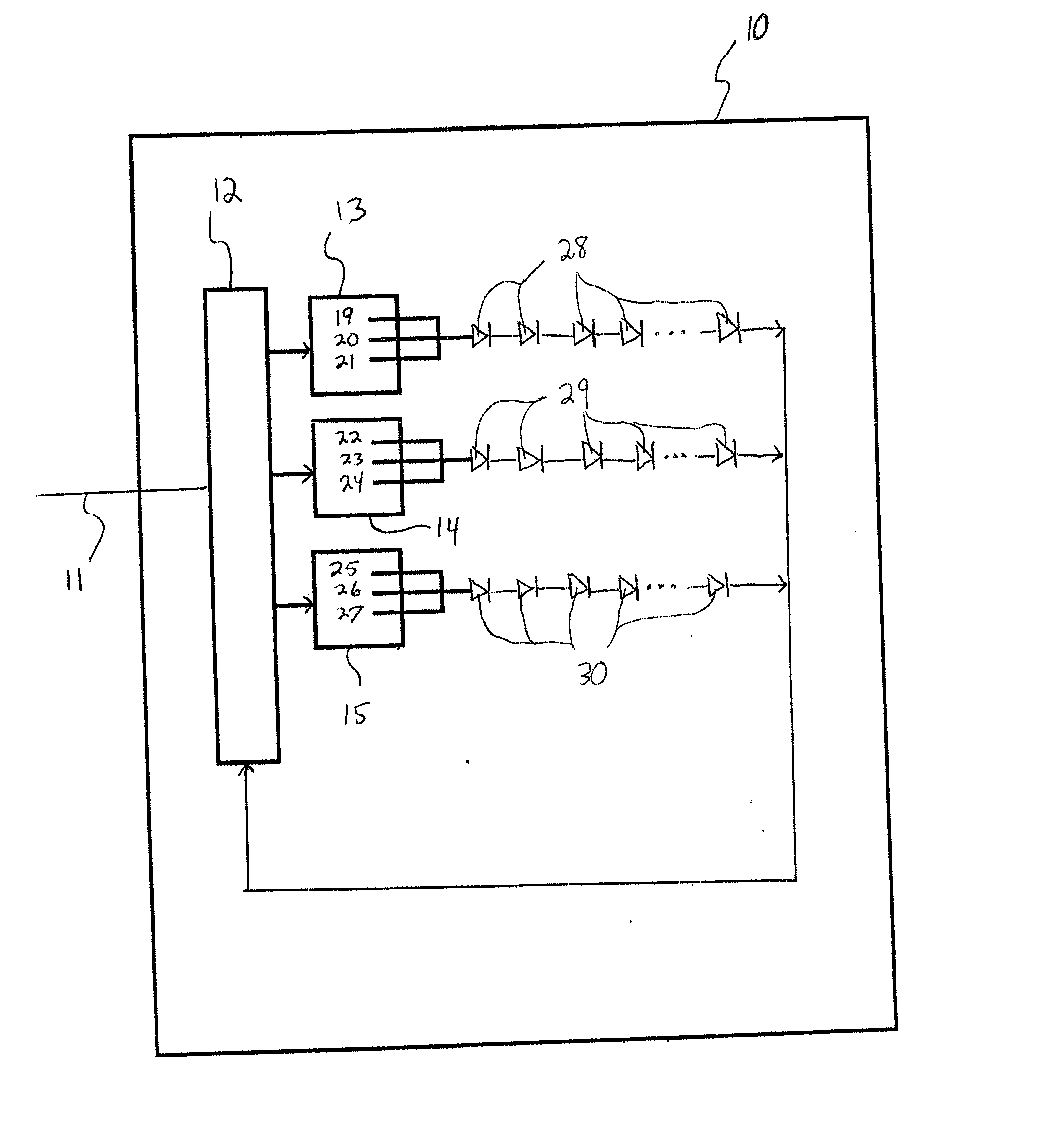
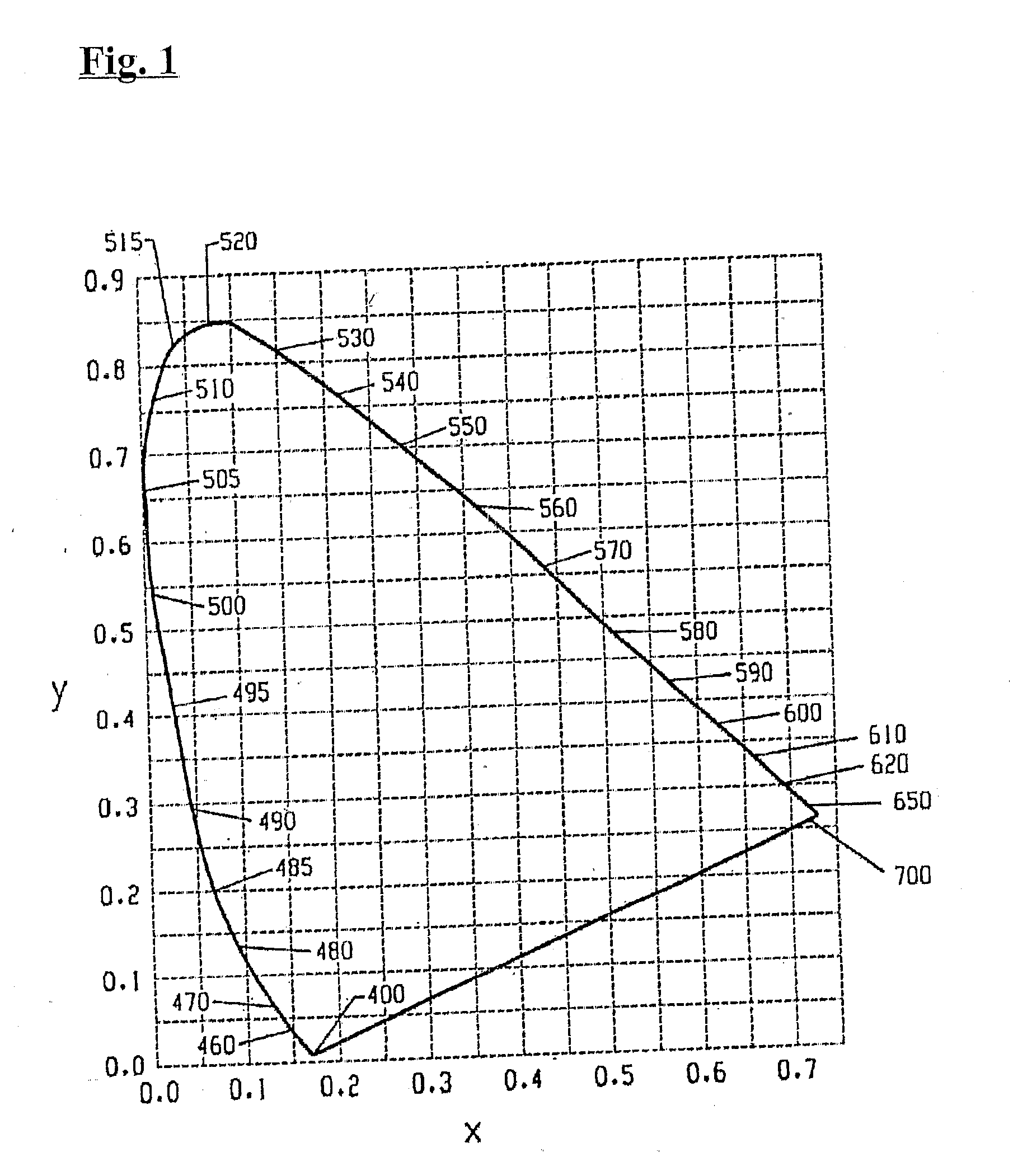
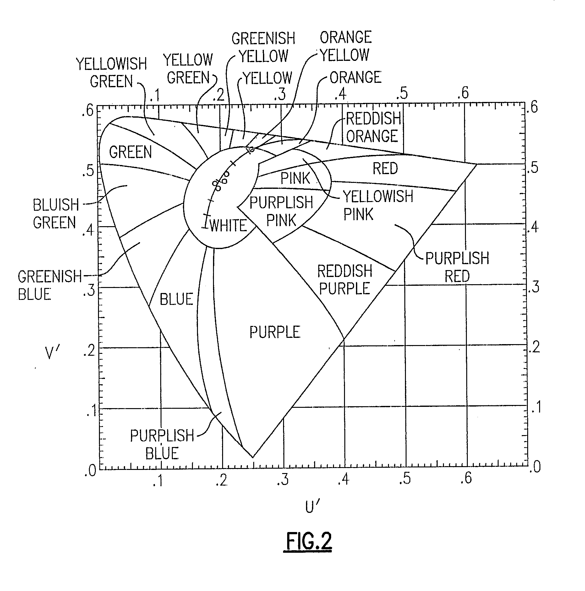
[0225]FIG. 4 is a schematic illustration of a lighting device in accordance with the present invention.

[0226] Referring to FIG. 4, AC current is supplied to the lighting device 10 via a cord 11. The lighting device includes a master currents regulator 12 which is switchable among three settings, a first master currents setting, a second master currents setting and a third master currents setting. The lighting device also includes a first current regulator 13, a second current regulator 14 and a third current regulator 15. The first current regulator 13 is electrically connected to a first series of light emitting diodes 16 which emit red light, the second current regulator 14 is electrically connected to a second series of light emitting diodes 17 which emit blue light, some of which is converted by lumiphors (positioned adjacent to the respective light emitting diodes 17), such the output light is green, and the third current regulator 15 is electrically connected to a third series...

second embodiment

[0242]FIG. 5 is a schematic illustration of a lighting device in accordance with the present invention.

[0243] The second embodiment is similar to the first embodiment, except that the second embodiment includes (1) a first series of light emitting diodes 28 which emit blue light, some of which is converted by lumiphors such that the output light is white (instead of the light emitting diodes 16 which emit red light), (2) a second series of light emitting diodes 29 which emit yellow light (instead of the light emitting diodes 17 and the associated lumiphors), and (3) a third series of light emitting diodes 30 which emit red light (instead of the light emitting diodes 18 which emit blue light).

third embodiment

[0244]FIG. 6 is a schematic illustration of a lighting device in accordance with the present invention.

[0245] The third embodiment is also similar to the first embodiment, except that the first series of light emitting diodes is represented as “A”, the second series of light emitting diodes is represented as “B”, and the third series of light emitting diodes is represented as “C”, to signify that the first, second and third series of light emitters can be of any desired respective colors, and the third embodiment also includes a current regulator identified as “N+1” to indicate that the device can include any desired number of groups of solid state light emitters and associated current regulators. For example, in representative additional embodiments: [0246] (1) “A” can signify a series emitters which emit white light, “B” can signify a series of emitters which emit yellow light, and “C” can signify emitters which emit red light; [0247] (2) “A” can signify a series emitters which em...


PUM


Abstract

A lighting device, comprising at least first and second current regulators, each switchable among two settings, and at least first and second groups of solid state light emitters. If the first regulator is in a first setting, a first current is supplied to the first group and a second current is supplied to the second group, and if the first regulator is in a second setting, a third current is supplied to the first group and a fourth current is supplied to the second group. In some embodiments, a ratio of the third current divided by the first current differ's from a ratio of the fourth current divided by the second current by at least 5 %. Also, a method comprising substantially simultaneously adjusting current supplied to a first group, and adjusting a current supplied to a second group.

Description

CROSS-REFERENCE TO RELATED APPLICATIONS [0001] This application claims the benefit of U.S. Provisional Patent Application No. 60 / 809,595, filed May 31, 2006, the entirety of which is incorporated herein by reference.FIELD OF THE INVENTION [0002] The present invention is directed to a lighting device, more particularly, a lighting device which can readily be operated so as to change the overall intensity of the light output from the lighting device. In particular, the invention relates to lighting devices which comprise one or more solid state light emitters and which minimize or avoid color change when the overall intensity of the light output from the device is changed. The present invention is also directed to methods of changing the overall intensity of light output from lighting devices. BACKGROUND OF THE INVENTION [0003] A large proportion (some estimates are as high as twenty-five percent) of the electricity generated in the United States each year goes to lighting. Accordingl...

Claims


Application Information

Patent Timeline
IPC IPC(8): G09G5/10H05B44/00
CPCH05B33/0827H05B45/46F21V23/00
Inventor NEGLEY, GERALD H.
Owner IDEAL IND LIGHTING LLC
Why Eureka
Try Eureka