Apparatus and Upwind Methods for Optical Flow Velocity Estimation

Inactive Publication Date: 2007-12-06
MURALI BEDDHU
View PDF8 Cites 30 Cited by
  • Summary
  • Abstract
  • Description
  • Claims
  • Application Information

AI Technical Summary

Benefits of technology

[0028]The OFC module uses one or more of the above disclosed upwind methods to calculate the optical flow velocity components regardless of whether the optical flow is 1D or 2D or 3D or whether the images are color or grayscale. It uses the same methods for calculating the velocity components in range flow problems.
[0029]The upwind methods for 1D, 2D and 3D, graysc

Problems solved by technology

Since the optical flow constraint is hyperbolic in nature, it is well known in hyperbolic solver prior art that, in general, central differencing based methods are either numerically oscillatory or outright unstable unless one explicitly adds stabilizing terms in the discretization process.
So, as discussed above, their initial velocity field will be error prone since they use the standard Horn and Schunck method to obtain it.
Since they use this velocity field to upwind the optical flow constraint later to o

Method used


Image

  • Apparatus and Upwind Methods for Optical Flow Velocity Estimation
  • Apparatus and Upwind Methods for Optical Flow Velocity Estimation
  • Apparatus and Upwind Methods for Optical Flow Velocity Estimation

Examples


Embodiment Construction

[0043]The following description presents preferred embodiments referring to the accompanying drawings which show specific embodiments that may be practiced, by way of illustration. These drawings are included heretofore as part of the description. It is clear, without departing from the scope of this specification, that other embodiments may also be practiced including structural changes made to the ones disclosed in this specification.

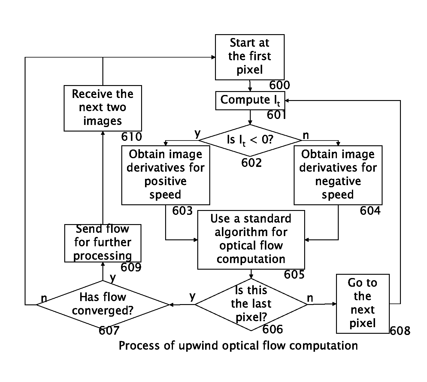
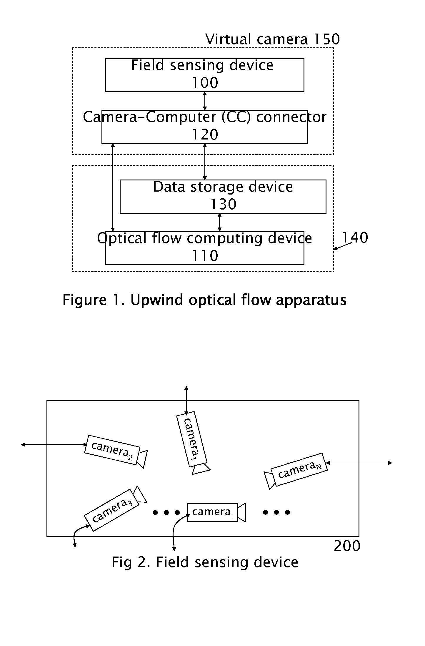
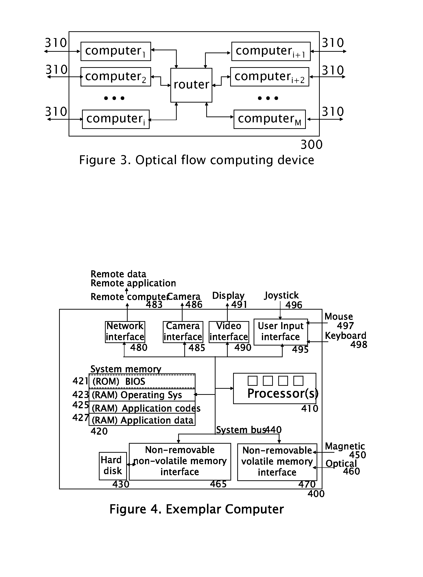
[0044]A system typically comprises of (1) a field sensing device that records a spatio-temporal distribution of an electromagnetic field or a mechanical / acoustic field, (2) a optical flow computing device that performs optical flow computations using upwind discretization-based image derivatives, (3) associated peripheral devices, and (4) internal and external interconnects that connect the field sensing device, the optical flow computing device and peripherals. In order to produce an optical flow, the system, either in whole or in part, may be statio...


PUM


Abstract

Apparatus and methods for estimating the optical flow velocity components using an upwind discretization are presented. In prior art, the knowledge of the signs of the optical flow velocity components is needed for using upwind discretization. But in optical flow computations the velocity components are precisely the unknowns and thus their sign information is not available. This invention discloses apparatus and methods in which upwinding is done based on the sign of the local time derivative instead of the signs of the optical flow velocity components.

Description

BACKGROUND OF THE INVENTION[0001]1. Technical Field[0002]This invention relates to fields such as computer vision, medical imaging (PET, CT, MRI, tagged MRI, fMRI, ultrasound, infrared, X-ray, UV / visible light fluorescence, Raman spectroscopy or microwave), hyperspectral imaging, Doppler radar, and related fields where estimation of either 1D or 2D or 3D optical flow velocity components or the range flow velocity components is of interest. Specifically, embodiments of this invention include methods, apparatus, computer software implementations and computer hardware implementations suitable for computing optical flow velocity components involving one or more spatial dimensions. In the case of 2D, the optical flow may be observed on a Euclidian (flat) or a Riemannian (curved) image surface. The methods apply to both grey scale and color images. One can further process such estimated optical flow velocity components to recover other information of interest such as, but not limited to, ...

Claims


Application Information

Patent Timeline
IPC IPC(8): G06K9/00
CPCG01P5/001G06T7/2066G01P5/26G06T7/269
Inventor MURALI, BEDDHU
Owner MURALI BEDDHU
Why Eureka
Try Eureka