Water turbine system and method of operation

a water turbine and water turbine technology, applied in the direction of machines/engines, electric generator control, final product manufacturing, etc., can solve the problems of reducing the tidal range inside the basin or lagoon, and reducing the transfer of water between the basin and the sea

Inactive Publication Date: 2007-12-13
NORTHERN POWER SYSTEMS INC
View PDF19 Cites 61 Cited by
  • Summary
  • Abstract
  • Description
  • Claims
  • Application Information

AI Technical Summary

Problems solved by technology

This design leads to a decrease in the tidal range inside the basin or l...

Method used


Image

  • Water turbine system and method of operation
  • Water turbine system and method of operation
  • Water turbine system and method of operation

Examples


Embodiment Construction

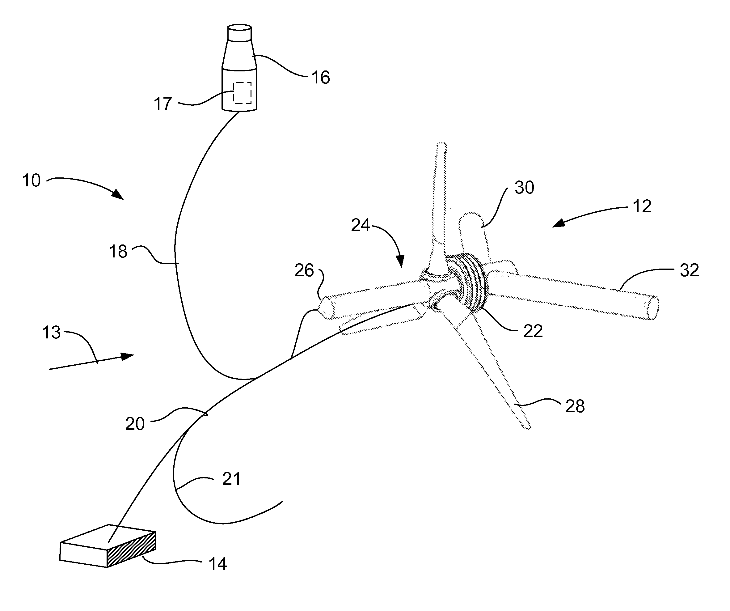
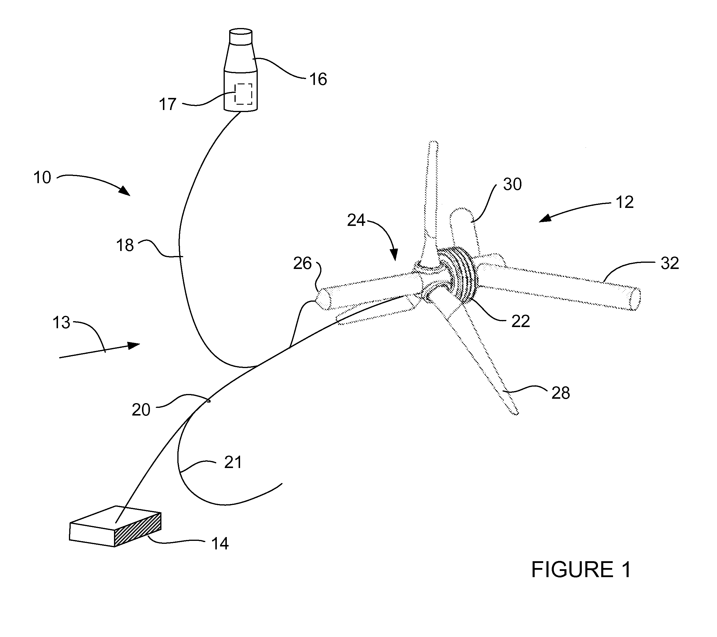
[0024]Referring now to FIG. 1, the water turbine system 10 is illustrated. The turbine system 10 includes a turbine structure 12 that is coupled to a mooring 14 and a floatation device 16. Depending on the environment of the location, the mooring 14 may be installed into the seabed floor as shown, or alternatively, the mooring that is heavy enough to prevent migration of the water turbine system 10 may be used. Once the mooring 14 is installed, and the buoy 16 is connected by cables 18 and 20, the turbine structure may be deployed or retrieved with relative ease as will be described in more detail below. These major components are connected together by flexible couplings, such as cables 18, 20, 21 as will be described in a more detail herein.

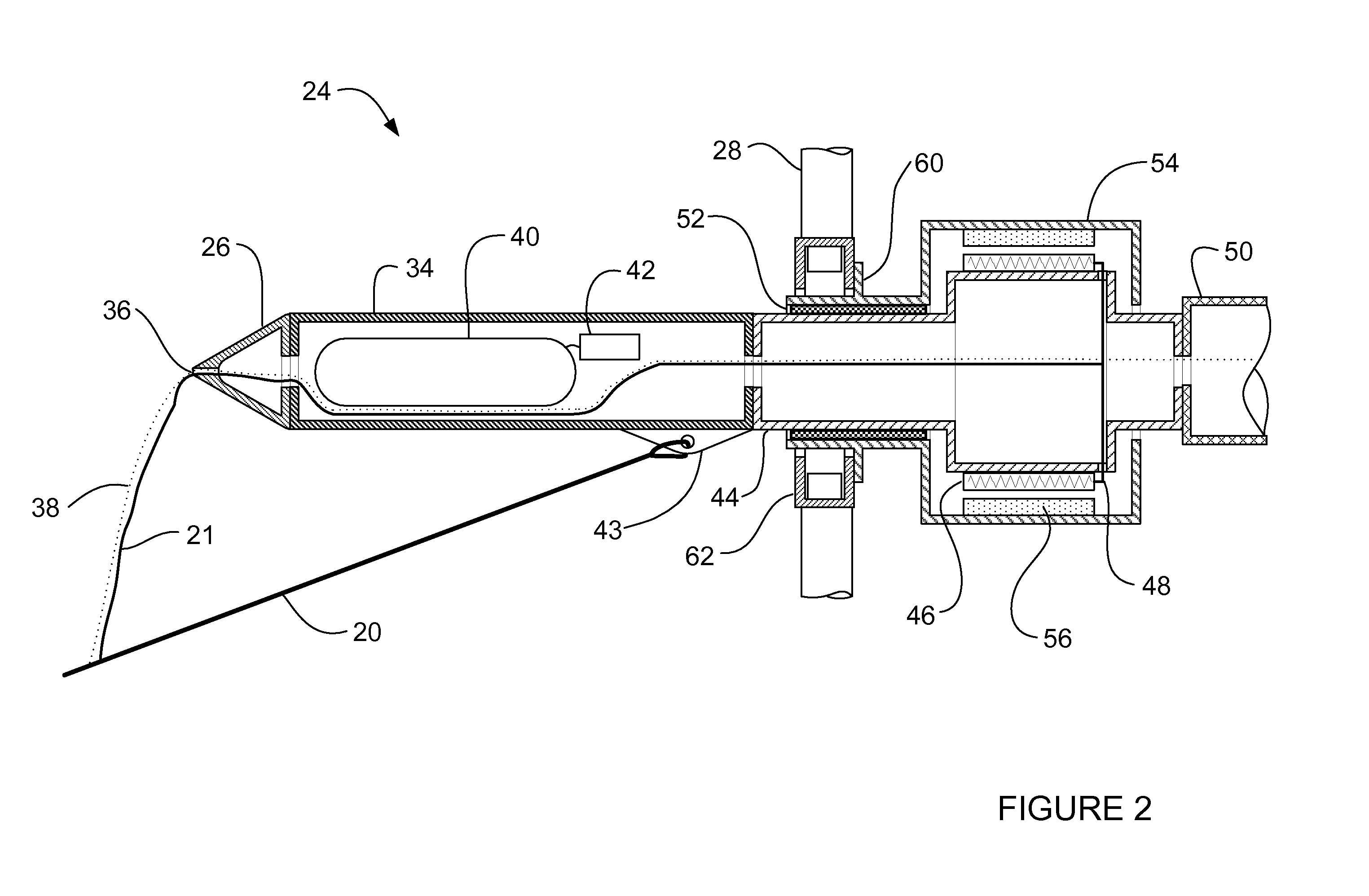
[0025]The turbine structure 12 further includes a first body portion 24 having a nose cone 26, a plurality of rotatable blades 28 that are coupled to a generator 22. A first body portion 30 and second body portion 32 extend on an angle from the ...


PUM


Abstract

A system for providing electrical power from a current turbine is provided. The system includes a floatation device and a mooring. A water turbine structure is provided having an upper and lower portion wherein the lower portion includes a water fillable chamber. A plurality of cables are used to couple the system where a first cable couples the water turbine to the mooring and a second cable couples the floatation device to the first cable. The system is arranged to allow the turbine structure to be deployed and retrieved for service, repair, maintenance and redeployment.

Description

FEDERAL RESEARCH STATEMENT[0001]This invention was made with Government support under contract DE-FG02-05ER84318 awarded by the Department of Energy. The Government has certain rights in this invention.FIELD OF INVENTION[0002]This disclosure relates generally to a system for generating electrical power with a water turbine system, and especially relates to a submergible water turbine system incorporating a system for easily positioning and servicing the water turbine.BACKGROUND OF THE INVENTION[0003]Oceans cover some 70% of the earth's surface. These bodies of water contain vast reservoir of energy mainly due to solar heating and wind stresses. If this energy couple be harnessed, a large portion of the worlds energy needs may be met in clean and renewable manner. Various devices have been developed to utilize this energy, including, ocean thermal energy conversion devices (OTEC), tidal power devices, wave power generators and flowing water (current) turbines.[0004]OTEC devices have ...

Claims


Application Information

Patent Timeline
IPC IPC(8): F03B13/00F03B13/10H02P9/04
CPCF03B17/061F05B2230/80F05B2240/914Y02E10/725F05B2240/93F05B2240/97Y02E10/28F05B2240/917F05B2240/9176Y02E10/30Y02E10/72Y02P70/50Y02E10/20
Inventor COSTIN, DANIEL P.
Owner NORTHERN POWER SYSTEMS INC
Why Eureka
Try Eureka