Method of auto focus

Inactive Publication Date: 2007-12-13
ASIA OPTICAL INT LTD
View PDF0 Cites 21 Cited by
  • Summary
  • Abstract
  • Description
  • Claims
  • Application Information

AI Technical Summary

Benefits of technology

[0026]Consequently, when performing the auto focus task, the driving unit only reverses once to make the image surface lying in the depth of field by moving the focusing lens and the sensing uni

Problems solved by technology

First, the traveling behavior of the focusing lens 101 is a shuttle run action as shown in FIG. 2 and FIG. 3. The five movement positions are A, B, C, D and E, and the B, C and D positions are transition positions. The focusing lens 101 needs to be moved in the opposite direction when it reaches the transition positions. Therefore, the driving unit 13 should be temporarily stopped, and then moves the focusing lens 101 towards the opposite direction. The shuttle run movement also wastes time and wears out the components thereby shortening the lifetime of the components and increasing the component failure rate.
Second, the focusing lens 101 moves between two positions

Method used


Image

  • Method of auto focus
  • Method of auto focus
  • Method of auto focus

Examples


Embodiment Construction

[0038]Reference will now be made in detail to the present preferred embodiments of the invention, examples of which are illustrated in the accompanying drawings. Wherever possible, the same reference numbers are used in the drawings and the description to refer to the same or like parts.

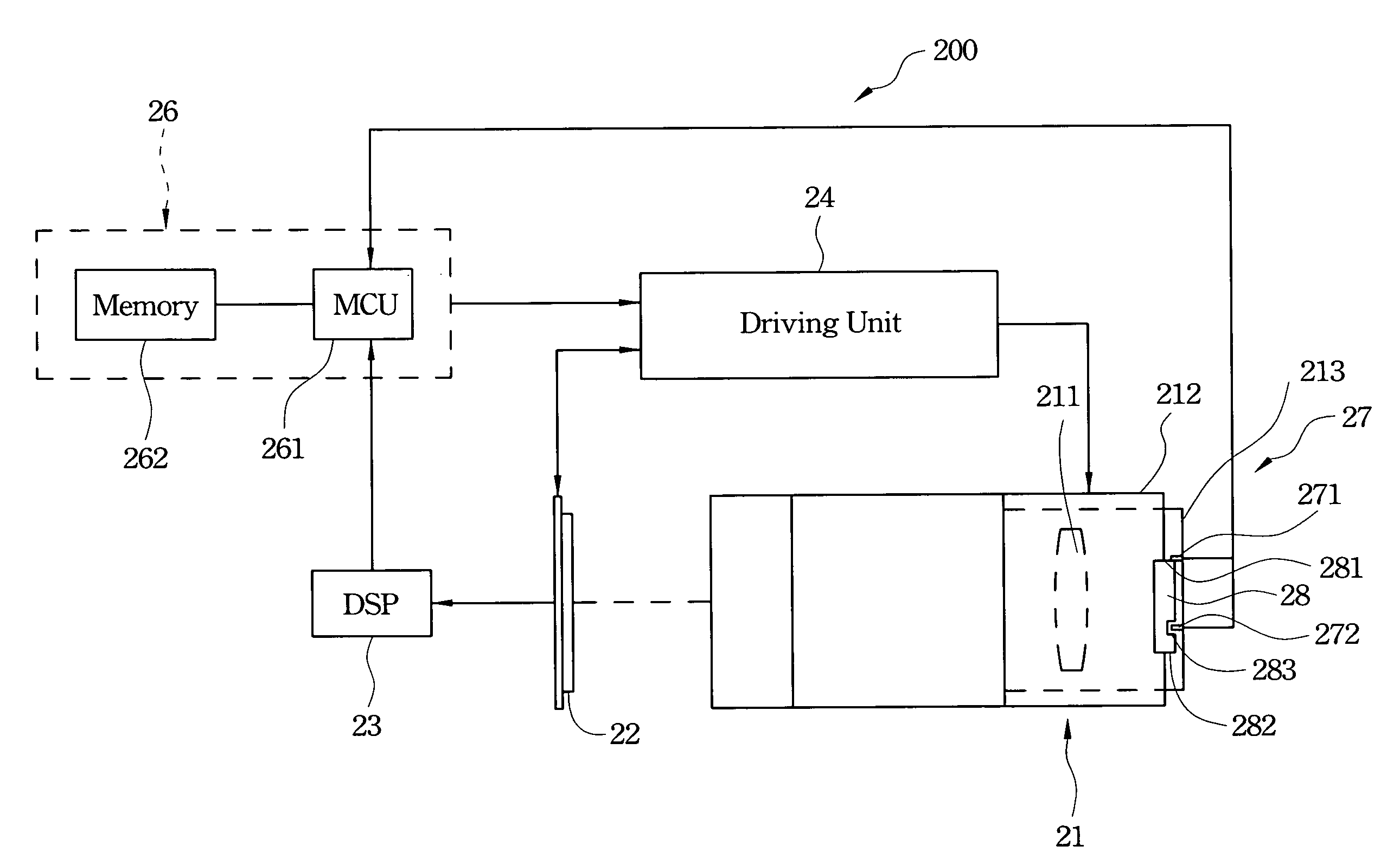
[0039]Refer to FIG. 4, FIG. 5 and FIG. 6. An embodiment of an auto focus method in accordance with the present invention is used for a photographic apparatus 200 to adjust the relative position between an optical system and a sensing unit 22. The adjustment makes an image surface lie in the range of the depth of field. The photographic apparatus 200 comprises the optical system, the sensing unit 22, a digital signal processor 23, a driving unit 24, a control unit 26 and a position decoding module 27. Wherein the digital signal processor 23 receives electric signals of the sensing unit 22. Wherein the driving unit 24 moves the optical system or the sensing unit 22. The control unit 26 connects electri...


PUM


Abstract

An auto focus method adapted to adjust relative positions between an optical system and a sensing unit so as to make an image surface lying in the depth of field is disclosed. The optical system includes at least a focusing lens. The method returns the focusing lens and the sensing unit to zero, change relative distances between the focusing lens and the sensing unit to evaluate evaluation values of lying the image surface in the depth of field, and adjusts towards the evaluation values until the image surface by the sensing unit lies in the depth of field to complete auto focus. When performing the task of auto focus, the driving unit only reverses once in shuttling runs. The auto focus method not only increases focusing speed, but also enhances precision and degree of wear resisting, which prolong lifetime of the apparatus.

Description

RELATED APPLICATIONS[0001]The application claims priority to Taiwan Application Serial Number 95116719, filed May 11, 2006, which is herein incorporated by reference.BACKGROUND[0002]1. Field of Invention[0003]The present invention relates to a method of adapting or adjusting so that objects can be caught clearly. More particularly, the present invention relates to a method of auto focusing a photographic apparatus.[0004]2. Description of Related Art[0005]Refer to FIG. 1, FIG. 2 and FIG. 3. Photographic apparatus 100 of digital cameras generally have an auto focus function to help a user to quickly catch an image surface lying within the depth of field. The photographic apparatus 100 includes a lens device 10 with a focusing lens 101, a sensing unit 11, a digital signal processor (DSP) 12, a driving unit 13 and a control unit 15. The driving unit 13 is connected to the sensing unit 11 and the focusing lens 101. The control unit 15 is electrically connected to the digital signal proce...

Claims


Application Information

Patent Timeline
IPC IPC(8): G03B13/00
CPCG02B7/36H04N5/23212G03B13/36H04N23/959H04N23/675
Inventor WU, TUNG-YING
Owner ASIA OPTICAL INT LTD
Why Eureka
Try Eureka