Zoom lens and imaging apparatus

a zoom lens and imaging apparatus technology, applied in the field of zoom lens and imaging apparatus, can solve the problems of large lens system, inability to correct aberration in a balanced manner, and large second lens group, so as to shorten the close distance imaging distance, avoid interference, and increase the speed of focusing operations

Inactive Publication Date: 2014-04-24
FUJIFILM CORP
View PDF2 Cites 4 Cited by
  • Summary
  • Abstract
  • Description
  • Claims
  • Application Information

AI Technical Summary

Benefits of technology

[0032]Hereinafter, these advantageous effects will be described in further detail. Conditional Formula (1) determines the ratio between the thicknesses of the first lens group and the second lens group. If the value of D2g / D1g is less than or equal to the lower limit defined in Conditional Formula (1), it will be necessary to configure the second lens group to be thin. As a result, the movement space of the image side second partial lens group during focusing operations will become small. Therefore, it will not be possible to shorten a close distance imaging distance at which focusing is possible at the telephoto end in order to avoid interference between the lenses and mechanical components. Alternatively, the first lens group will become excessively thick, which is not preferable. Inversely, if the value of D2g / D1g is greater than or equal to the upper limit defined in Conditional Formula (1), the second lens group will become thick, resulting in the total length and the thickness during retraction to become thick. This is not preferable from the viewpoint of miniaturization and increasing the speed of focusing operations. Alternatively, it will become necessary to form the first lens group to be thin. This will necessitate inordinately decreasing a spatial distance necessary for correcting aberrations. Therefore, it will become difficult to correct distortion and field curvature at the wide angle end, and is not preferable.
[0033]Meanwhile, Conditional Formula (2) determines the distance between the object side partial second lens group and the image side partial second lens group when focused on infinity at the telephoto end as a ratio with the focal length of the entire system at the telephoto end. If the value of D2t / ft is less than or equal to the lower limit defined in Conditional Formula (2), the movement space will decrease. This will result in the minimum imaging distance at the telephoto end not being able to be shortened as described previously, and is not preferable. In order to decrease the minimum imaging distance in such a case, it will become necessary to increase the power of the image side partial second lens group, which is not preferable because correction of spherical aberrations will become difficult.
[0034]The above shortcomings can be prevented in the case that Conditional Formulae (1) and (2) are satisfied, and the aforementioned advantageous effects can be obtained. The advantageous effects obtained by satisfying Conditional Formula (1) will become more prominent if Conditional Formula (1′) is satisfied within the range defined in Conditional Formula (1).
[0035]Meanwhile, the second zoom lens according to the present invention is of a configuration in which focusing is performed by moving the image side partial second lens group along an optical axis; and satisfies Conditional Formulae (3) and (4). Therefore, the second zoom lens according to the present invention exhibits the advantageous effects that a variable magnification ratio of 3× to 5× can be secured, focusing operations can be performed at high speed, variations in aberrations during focusing operations can be suppressed, and sufficient miniaturization is enabled.
[0036]Hereinafter, these advantageous effects will be described in further detail. Conditional Formula (3) determines the relationship between the focal length of the entire system at the telephoto end and the focal length of the first lens group. If the value of ft / |f1| is less than or equal to the lower limit defined in Conditional Formula (3), the amount of movement when changing magnification will become great, the total length of the lens will become great, and is not preferable because the lens system will become large. Inversely, if the value of ft / |f1| is greater than or equal to the upper limit defined in Conditional Formula (3), correction of field curvature at the wide angle end will become difficult, which is not preferable.
[0037]Conditional Formula (4) determines the relationship between the focal length of the entire system at the telephoto end and the focal length of the second lens group. If the value of ft / f2 is less than or equal to the lower limit defined in Conditional Formula (4), the amount of movement when changing magnification will become great, and is not preferable because the lens system will become large. Inversely, if the value of ft / f2 is greater than or equal to the upper limit defined in Conditional Formula (4), it will become necessary to increase the power of the second lens group, which is not preferable because correction of spherical aberrations will become difficult.

Problems solved by technology

It becomes necessary to secure a large space to accommodate such movement, and the lens system becomes large.
However, if the power of the focusing lens becomes excessively great, it will not be possible to correct aberrations in a balanced manner.
However, in the conventional zoom lenses disclosed in Japanese Unexamined Patent Publication No. 2007-279232, U.S. Pat. No. 6,124,987, U.S. Pat. No. 6,351,337, U.S. Pat. No. 6,968,128, U.S. Pat. No. 6,654,180, Japanese Unexamined Patent Publication No. 2007-025373, and U.S. Pat. No. 7,576,924, there are those in which the optical performance and focusing performance are favorable but variable magnification ratios are small, the amounts of focusing movement are excessively great, or the number of lenses that constitute the second lens group is great, resulting the second lens group becoming extremely large.

Method used


Image

  • Zoom lens and imaging apparatus
  • Zoom lens and imaging apparatus
  • Zoom lens and imaging apparatus

Examples


Embodiment Construction

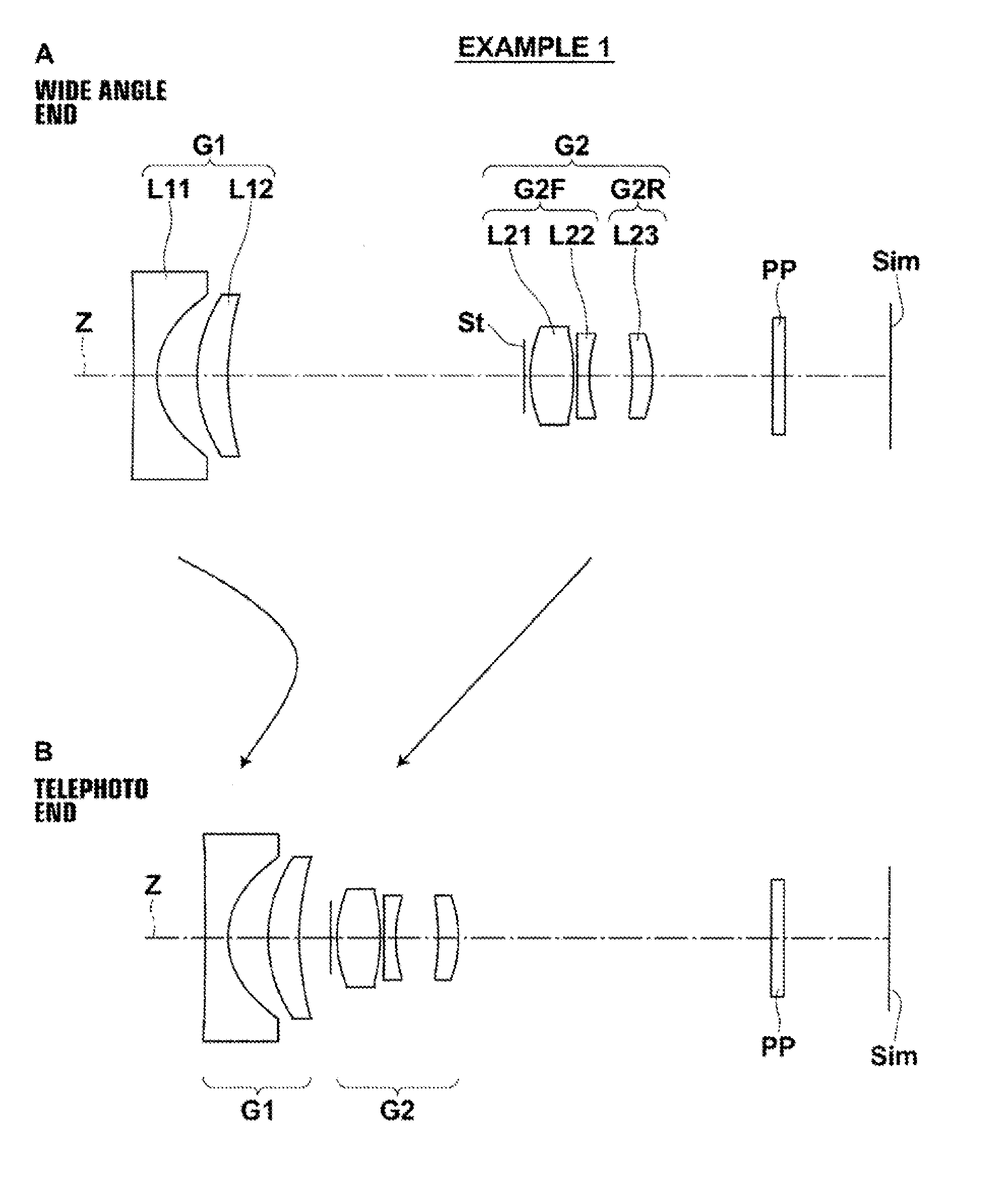
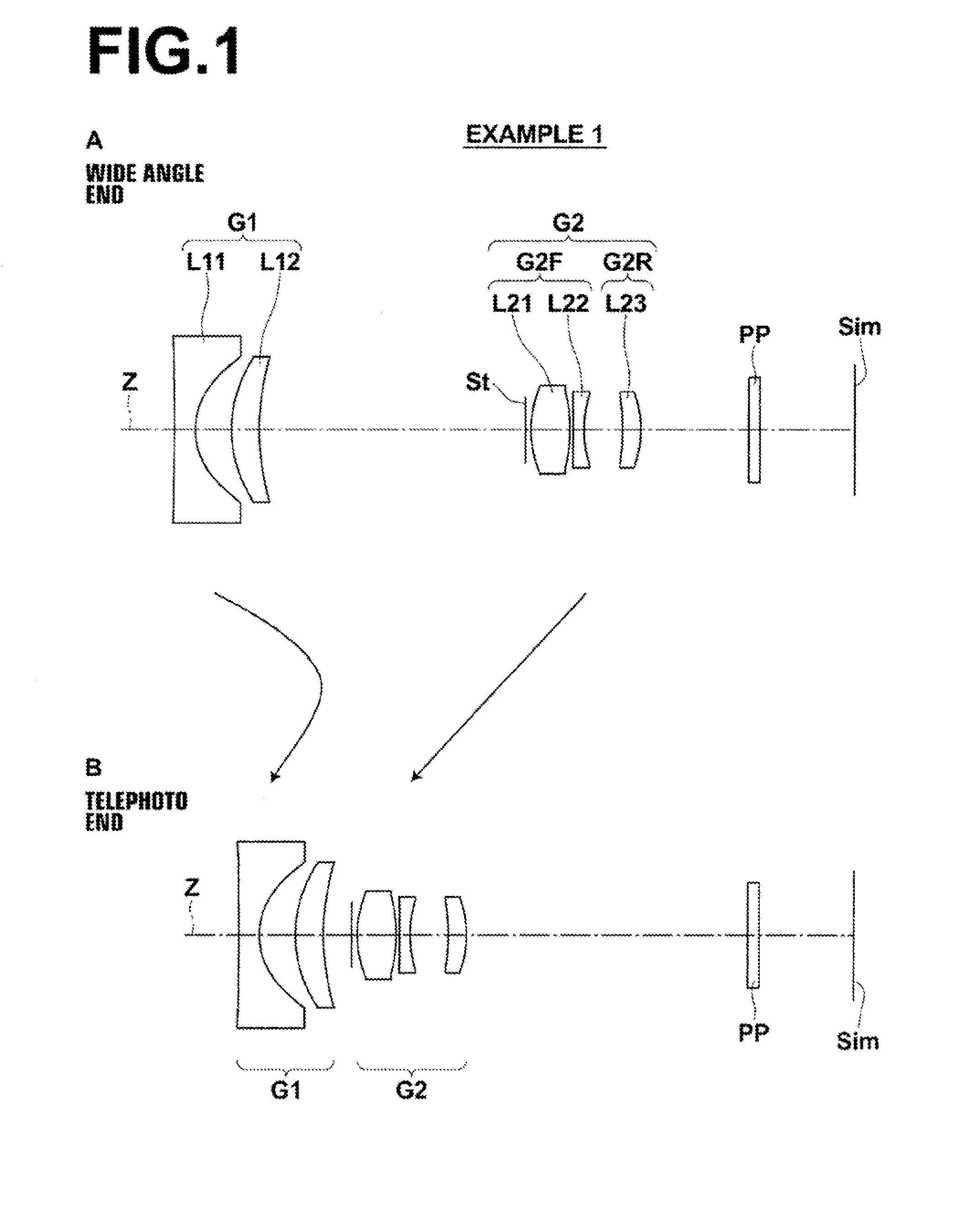
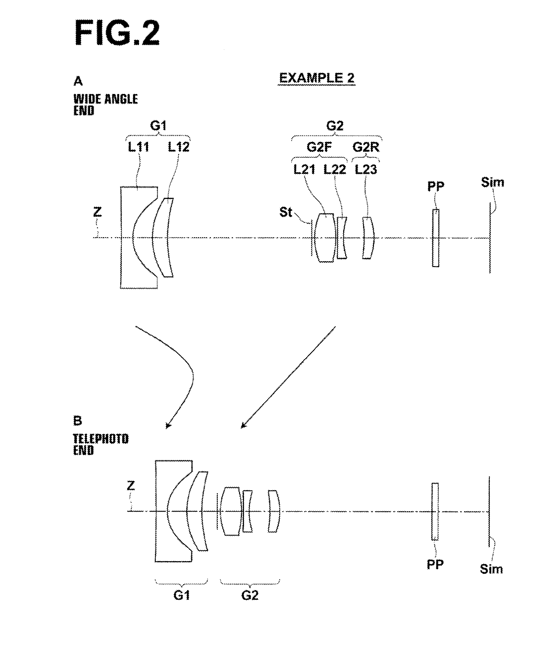
[0065]Hereinafter, embodiments of the present invention will be described in detail with reference to the attached drawings. FIG. 1 is a cross sectional diagram that illustrates the configuration of a zoom lens according to an embodiment of the present invention, and corresponds to a zoom lens of Example 1 to be described later. FIG. 2 through FIG. 6 and FIG. 8 are cross sectional diagrams that illustrate configurations of zoom lenses according to other embodiments of the present invention, and corresponds to zoom lenses of Examples 2 through 6 and 8 to be described later. FIG. 7 is a cross sectional diagram that illustrates the configuration of a zoom lens, which is a reference example with respect to the present invention. The basic configurations of the embodiments illustrated in FIG. 1 through FIG. 8 are the same. The manners in which the configurations are illustrated are also the same. Therefore, the zoom lenses according to the embodiments of the present invention will be des...


PUM


Abstract

A zoom lens includes: a first lens group having a negative power; and a second lens group having a refractive power, in this order from an object side. The zoom lens satisfies the following conditional formulae: 1.0<D2g/D1g<1.6, 0.08<D2t/ft<0.19, 1.15≦ft/|f1|<1.8, and 1.1<ft/f2<1.9, wherein D1g is the distance from a most object side lens surface to a most image side lens surface within the first group, D2g and D2t are the distance from a most object side lens surface to a most image side lens surface within the second group and the distance between an object side partial second lens group and an image side partial second lens group when focused on infinity at a telephoto end, respectively, ft is the focal length of the entire system at the telephoto end, and f1 and f2 are the focal lengths of the first group and the second group, respectively.

Description

TECHNICAL FIELD [0001]The present invention is related to a zoom lens and an imaging apparatus. Particularly, the present invention is related to a zoom lens which can be favorably utilized in miniature cameras and portable terminal devices, and to an imaging apparatus equipped with such a zoom lens.BACKGROUND ART [0002]Conventionally, zoom lenses of the two group or the three group type having leading negative lens groups (a configuration in which negative lens groups are provided toward the object side) are well known as zoom lenses to be provided in compact digital cameras, compact video cameras, and portable terminal devices. The rear focus method, in which the weight of lenses can be decreased compared to the front focus method, is often employed as the focusing method of such zoom lenses.[0003]Several focusing methods have also been proposed, in which only a portion of a plurality of lens groups or only a single lens is moved to perform focusing operations instead of moving th...

Claims


Application Information

Patent Timeline
Patent Type & Authority Applications(United States)
IPC IPC(8): G02B15/177
CPCG02B15/177G02B15/142G02B15/1425G02B15/20G02B13/0045G02B13/001G02B13/04G02B13/18G02B3/02G02B15/22G02B13/009H04N23/69
Inventor KAWAMURA, DAIKI
Owner FUJIFILM CORP
Why Eureka
Try Eureka