Optical Part Holding Unit
- Summary
- Abstract
- Description
- Claims
- Application Information
AI Technical Summary
Benefits of technology
Problems solved by technology
Method used
Image
Examples
Example
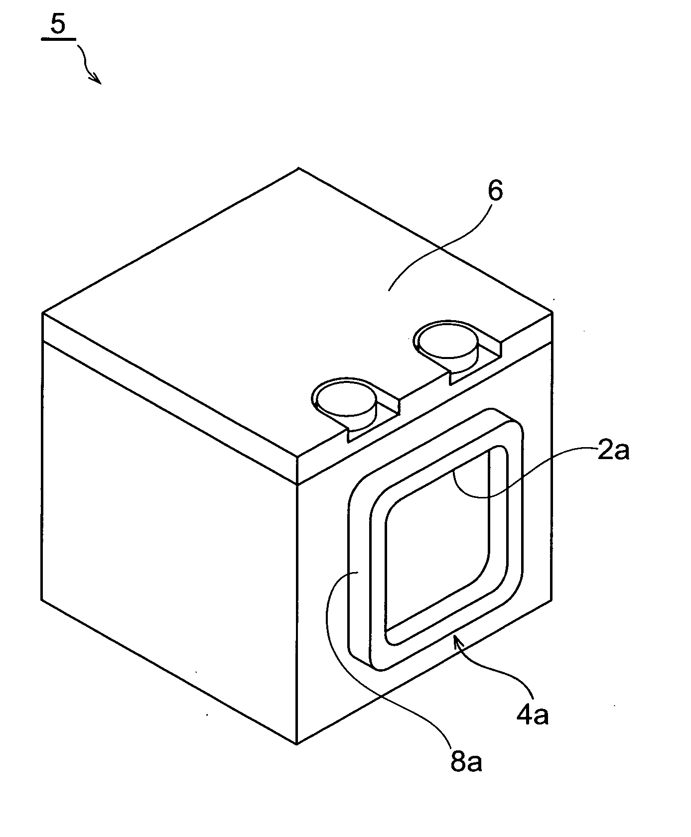
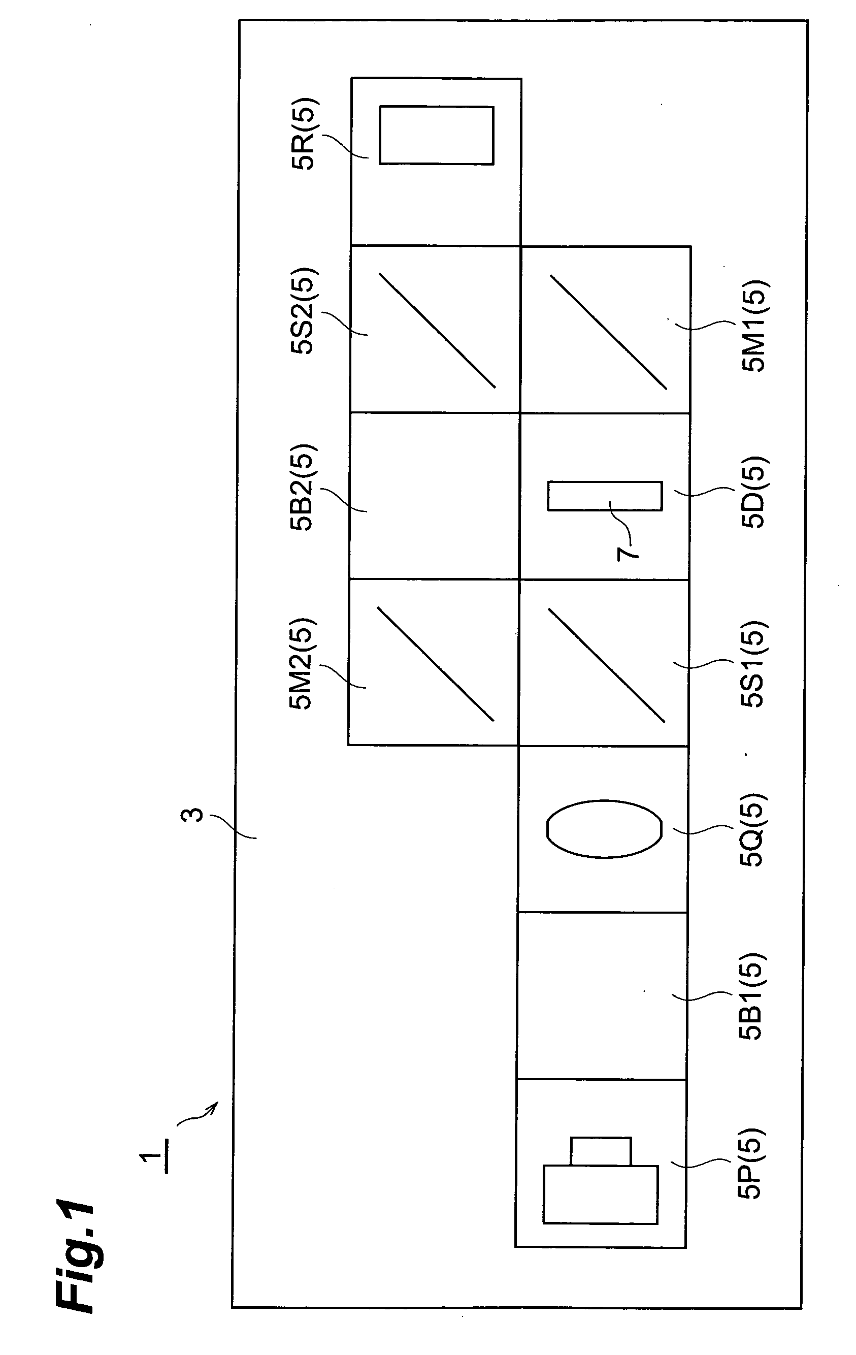
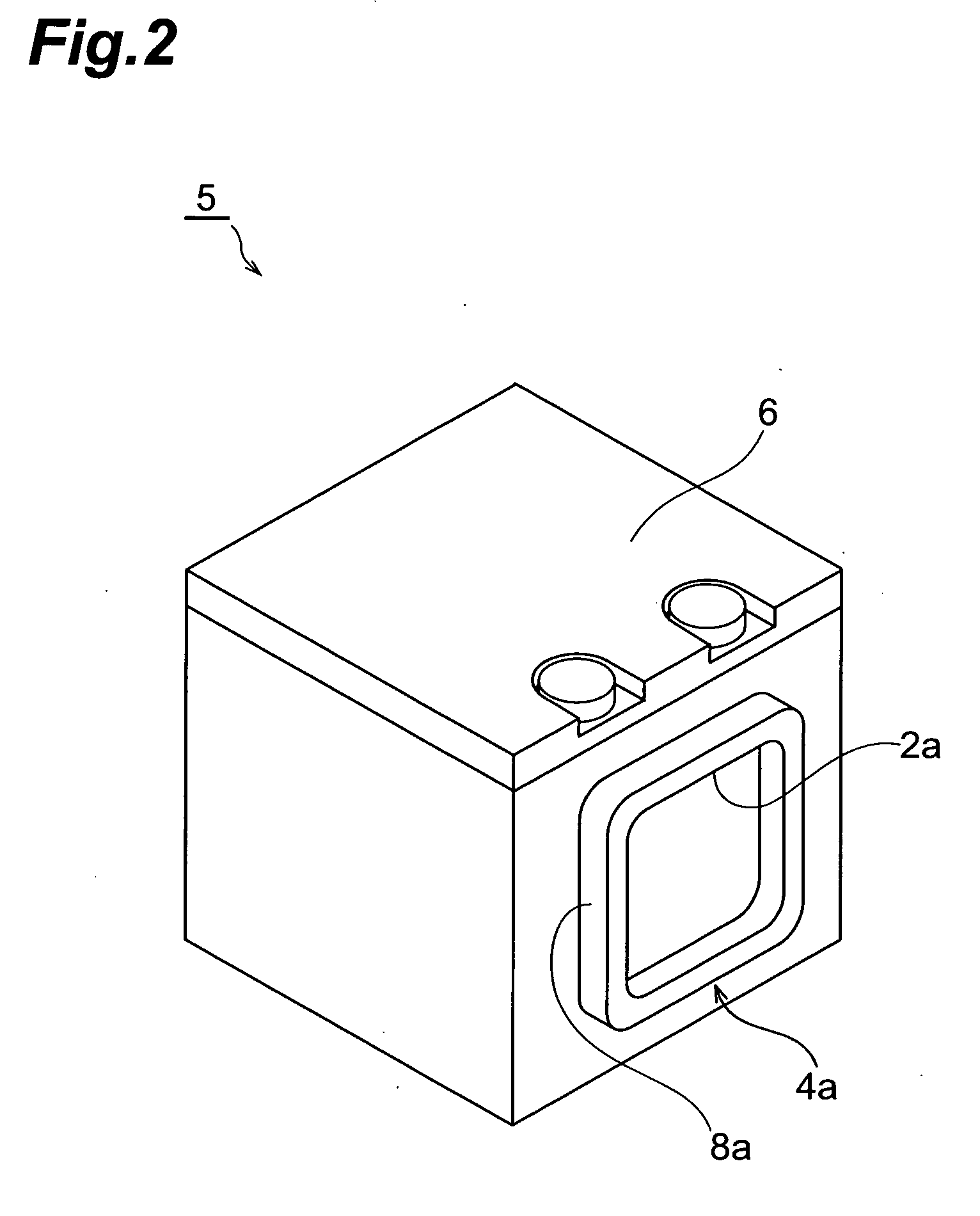
[0030] An optical component holding unit according to a preferred first embodiment of the present invention will hereinafter be described with reference to FIG. 1 to FIG. 3. FIG. 1 is a schematic planar block diagram showing a Mach-Zehnder interferometer provided with optical component holding units according to the first embodiment of the present invention, and FIG. 2 and FIG. 3 are perspective views showing optical component holding units in FIG. 1. It is noted that in the descriptions of the drawings, identical or equivalent elements are designated by the same reference numerals to omit redundant description.
[0031] As shown in FIG. 1, the Mach-Zehnder interferometer 1, which is used for, for example, measuring the amount of distortion of a transparent body, includes a mounting base 3 and various optical component holding units (hereinafter described in detail) 5.
[0032] The mounting base 3 is made of metal such as aluminum and is a substrate formed in a plate shape.
[0033] The v...
Example
[0045] In accordance with the thus arranged second embodiment, the fitting between the circular convex portion 11a and the circular hole 11b guides optical component holding units 15 to predetermined positions and couples the units detachably to each other for positioning in the three-dimensional direction, while the fitting between the spring pins 13a and the fitting holes 13b restrains the units relatively in the rotation direction for positioning in the rotation direction. It is therefore possible to exhibit the same effects as in the first embodiment.
[0046] Moreover, the spring pins 13a have an outside diameter of 1.6 mm and a length of 5 mm; the support holes 16a have an inside diameter of 1.54 mm and a depth of 2 mm; the fitting holes 13b have an inside diameter of 1.66 mm and a depth of 3.5 mm. Thus, when the fitting between the optical component holding units 15 is released, the spring pins 13a cannot be left in the corresponding fitting holes 13b to remain inserted in the ...
Example
[0048] In accordance with the thus arranged third embodiment, not only the fitting between the rectangular convex portion 8a and the rectangular hole 8b but also the fitting between the circular convex portion 11a and the circular hole 11b guides optical component holding units 25 to predetermined positions for more reliable positioning in the three-dimensional direction. It is therefore possible to improve the positioning accuracy in the three-dimensional direction relative to the first embodiment.
[0049] It is noted that in the foregoing embodiment, although the fitting shape 24a including the circular convex portion 11a inside the rectangular convex portion 8a and the fitting shape 24b including the circular hole 11b inside the rectangular hole 8b are provided, a fitting shape including a rectangular convex portion inside a circular convex portion and a fitting shape including a rectangular hole inside a circular hole may be provided.
[0050]FIG. 8 and FIG. 9 are perspective views...
PUM
Abstract
Description
Claims
Application Information
- R&D Engineer
- R&D Manager
- IP Professional
- Industry Leading Data Capabilities
- Powerful AI technology
- Patent DNA Extraction
Browse by: Latest US Patents, China's latest patents, Technical Efficacy Thesaurus, Application Domain, Technology Topic.
© 2024 PatSnap. All rights reserved.Legal|Privacy policy|Modern Slavery Act Transparency Statement|Sitemap