Multilayer mirror, evaluation method, exposure apparatus, device manufacturing method

a multi-layer mirror and exposure apparatus technology, applied in the field of multi-layer mirrors, evaluation methods, exposure apparatuses, can solve the problems of deterioration of optical characteristics, imaging characteristics, and limitations of lithography using uv light, and achieve excellent optical characteristics and easy examination or evaluation of stress compensation layers

Inactive Publication Date: 2007-12-13
CANON KK
View PDF5 Cites 21 Cited by
  • Summary
  • Abstract
  • Description
  • Claims
  • Application Information

AI Technical Summary

Benefits of technology

[0016]The present invention is directed to a multilayer mirror and an evaluation method, which can easily examine or evaluate a stress compensation layer, and realizes an excellent optical characteristic, such as an imaging characteristic.

Problems solved by technology

However, the lithography using the UV light has limits in view of the recent increasingly miniaturized semiconductor devices.
The light absorption in a material becomes conspicuous in the EUV region, and a refraction type optical element or dioptric system that utilizes refractions of the light used for the visual light and the UV light is no longer practical.
As a result, the optical characteristic, such as an imaging characteristic, of the multilayer mirror deteriorates.
Nevertheless, the stress compensation layer that does not maintain a desired precision cannot cancel out the stress of the reflection layer, leaving the deformation of the substrate, and further deforming the substrate.
However, the stress compensation layer is formed between the substrate and the reflection layer, and it is very difficult to examine the stress compensation layer in a non-destructive manner.
In addition, an evaluation of the reflected wavefront of a single multilayer mirror is very difficult, and an evaluation method that can easily evaluate the multilayer mirror is sought.

Method used


Image

  • Multilayer mirror, evaluation method, exposure apparatus, device manufacturing method
  • Multilayer mirror, evaluation method, exposure apparatus, device manufacturing method
  • Multilayer mirror, evaluation method, exposure apparatus, device manufacturing method

Examples


Embodiment Construction

[0033]Referring now to the accompanying drawings, a description will be given of an embodiment of the present invention. In each figure, the same reference numeral designates the same element, and a duplicate description thereof will be omitted.

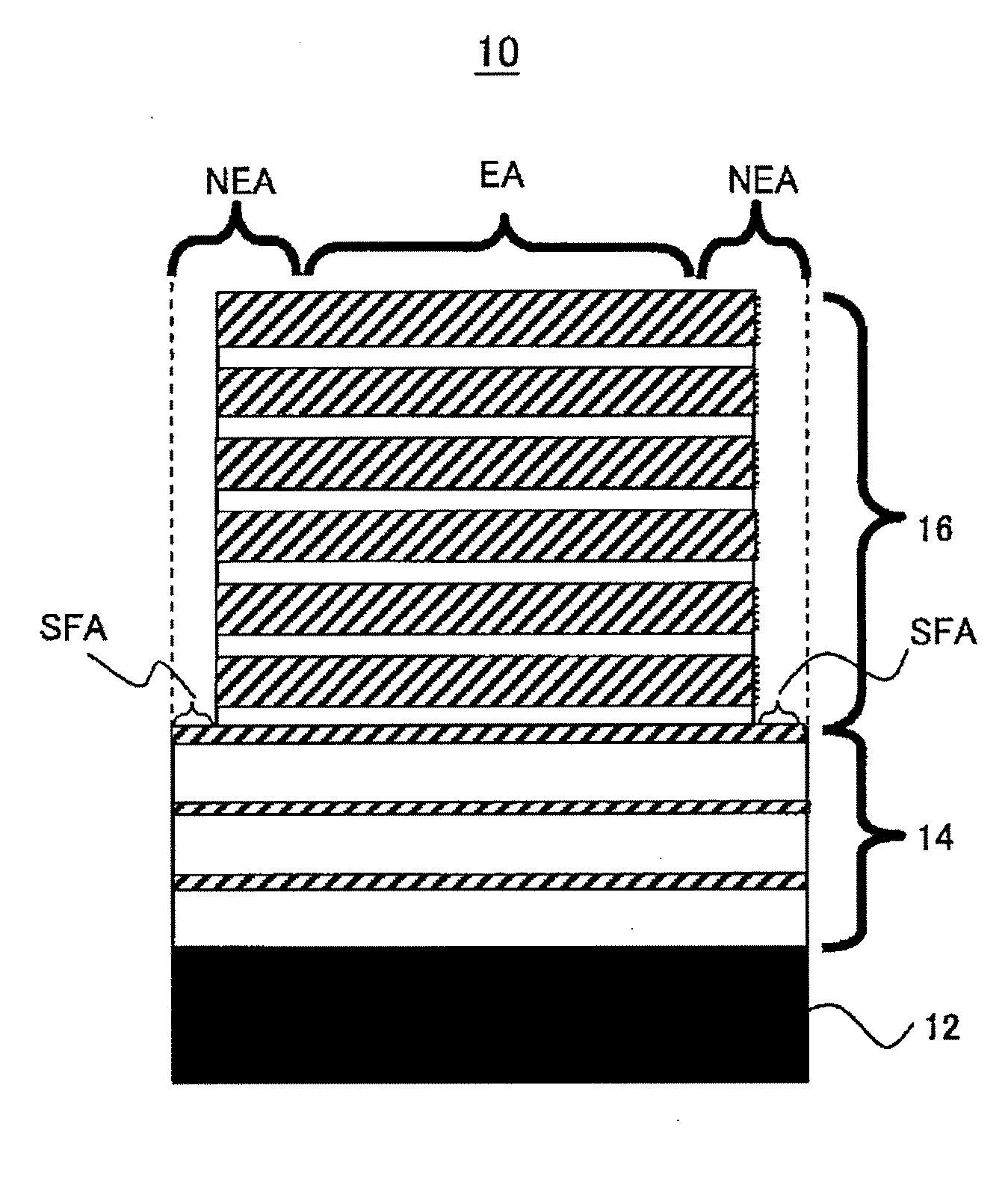
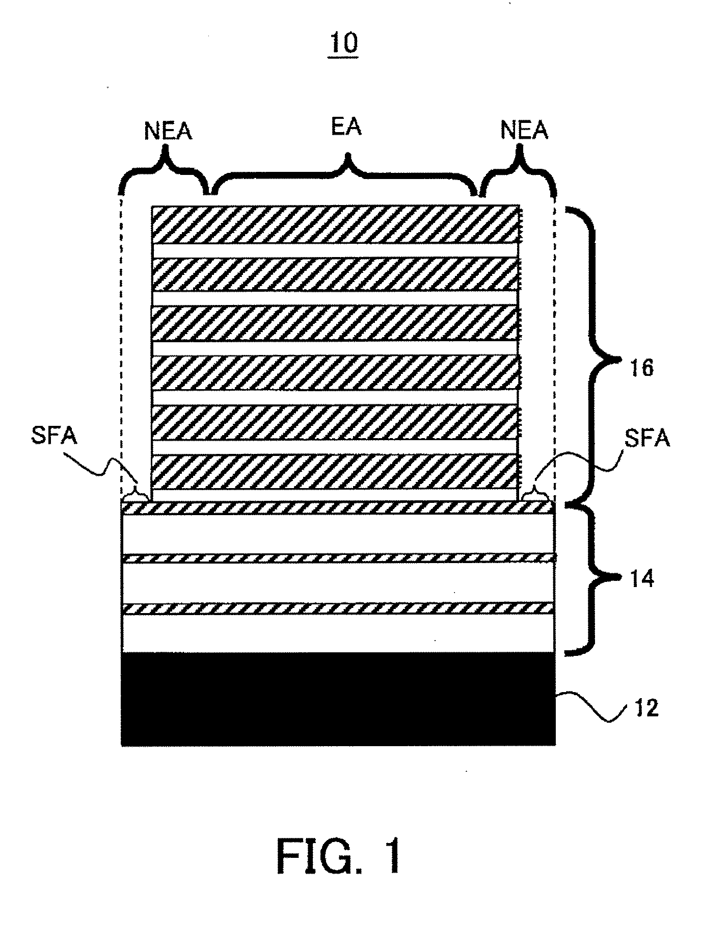
[0034]FIG. 1 is a schematic sectional view showing a structure of the multilayer mirror 10 according to one aspect of the present invention. The multilayer mirror 10 is a mirror that reflects the EUV light and is used for the EUV light wavelength range. The multilayer mirror 10 includes a substrate 12, a stress compensation layer 14, and a reflection layer 16. While FIG. 1 schematically illustrates the stress compensation layer 14 and the reflection layer 16, the actual stress compensation layer has 10 to 30 pairs of layers, and the actual reflection layer has 30 to 70 pairs of layers.

[0035]The substrate 12 is made of a material, such as low thermal expansion glass and silicon carbide, which has high rigidity and hardness and a small coeffici...


PUM

PropertyMeasurementUnit
wavelengthaaaaaaaaaa

Abstract

A multilayer mirror used for EUV light includes a substrate, a reflection layer for reflecting the EUV light, a stress compensation layer, formed between the substrate and the reflection layer, for compensating a deformation of the substrate by the reflection layer, wherein the substrate has a first area, in which the stress compensation layer is layered but no reflection layer is layered.

Description

BACKGROUND OF THE INVENTION[0001]1. Field of the Invention[0002]The present invention relates to a multilayer mirror, an evaluation method, and an exposure apparatus.[0003]2. Description of the Related Art[0004]In manufacturing a fine semiconductor device using the photolithography technology, a conventional projection exposure apparatus projects and transfers a circuit pattern of a mask (reticle) onto a wafer via a projection optical system.[0005]The minimum size (or resolution) transferable by the projection exposure apparatus is in proportion to the wavelength of the light used for the exposure, and inversely proportional to the numerical aperture (“NA”) of the projection optical system. Therefore, use of a shorter wavelength improves the resolution, and the use of a shorter wavelength of the exposure light is promoted along with the recent demand for fine processing to semiconductor devices. More specifically, use of a short wavelength of the ultraviolet (“UV”) light as the expo...

Claims


Application Information

Patent Timeline
Patent Type & Authority Applications(United States)
IPC IPC(8): G21K5/00G03F1/00G02B5/08G03F1/24G03F1/68G03F7/207G21K1/06H01L21/027
CPCB82Y10/00G21K2201/067G21K1/062G03F7/70958H01L21/0274
Inventor MASAKI, FUMITAROMIYAKE, AKIRA
Owner CANON KK
Why Eureka
Try Eureka