Intevertebral implant with reduced contact area and method

Inactive Publication Date: 2005-02-15
ZIMMER SPINE INC
View PDF58 Cites 107 Cited by
  • Summary
  • Abstract
  • Description
  • Claims
  • Application Information

AI Technical Summary

Benefits of technology

An implant of the invention provides a reduced displacement volume relative to the insertion bore necessary to accommodate the implant. The central support member or transverse members can also include openings which further reduce the displacement v

Problems solved by technology

Chronic back problems cause pain and disability for a large segment of the population.
When the disk material is diseased, the opposing vertebrae may be inadequately supported, resulting in persistent pain.
For example, the greater the overall contact area of the device with the surface of the bore, the slower the rate at which new bone can grow into the bore to stabilize the joint.
This lack of continuity of bone can translate into reduced structural integrity of the bony union.
Furthermore, reducing the amount and continuity of

Method used


Image

  • Intevertebral implant with reduced contact area and method
  • Intevertebral implant with reduced contact area and method
  • Intevertebral implant with reduced contact area and method

Examples


first embodiment

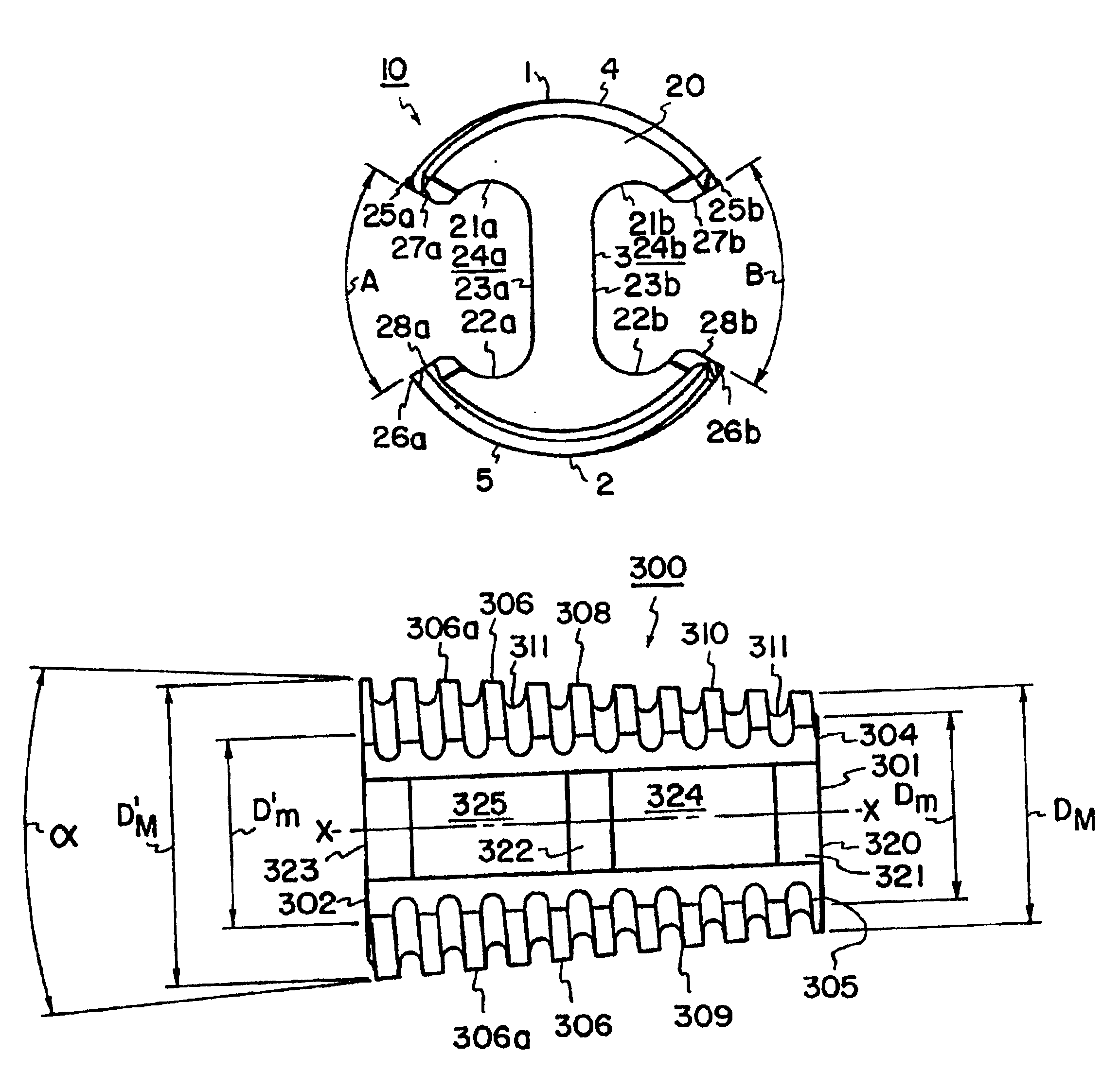
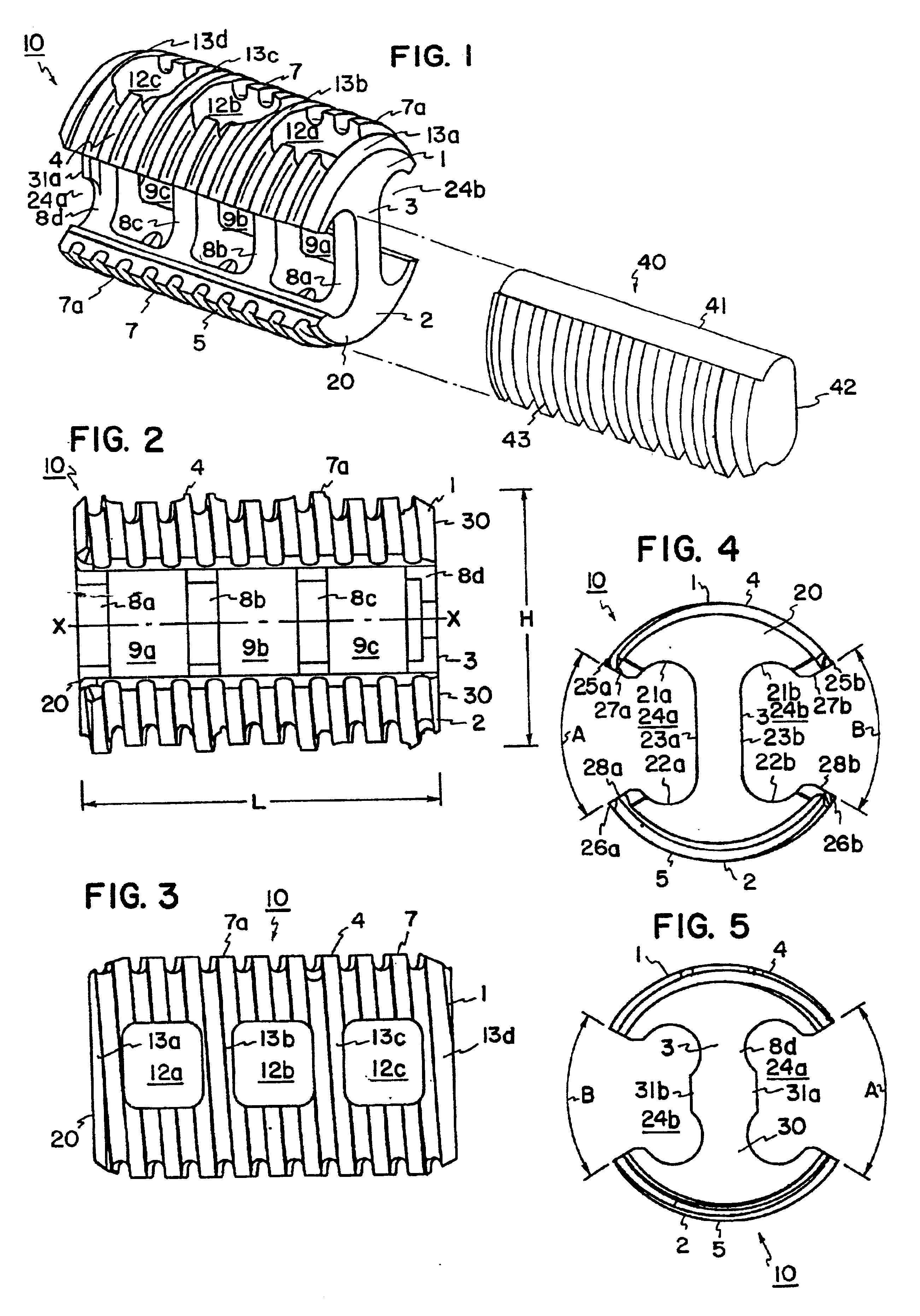
FIGS. 1-5 illustrate an implant of the invention having a first transverse member 1 and a second transverse member 2 spaced apart by a central support member 3. When inserted between opposing vertebrae, each transverse member is oriented transverse to the longitudinal axis of the vertebral column and the central support member is oriented parallel to the longitudinal axis of the vertebral column. Thus, the transverse members can also be referred to as a “cranial transverse member” and a “caudal transverse member” to indicate that when inserted between opposing vertebrae, one transverse member is oriented cranially and the other transverse member is oriented caudally.

The first transverse member 1 has a first bearing surface 4 and the second transverse member 2 has a second bearing surface 5. The first bearing surface 4 and the second bearing surface 5 include a pattern 7 for anchoring the implant within an insertion bore. The illustrated pattern 7 is a portion of a helical thread 7a ...

second embodiment

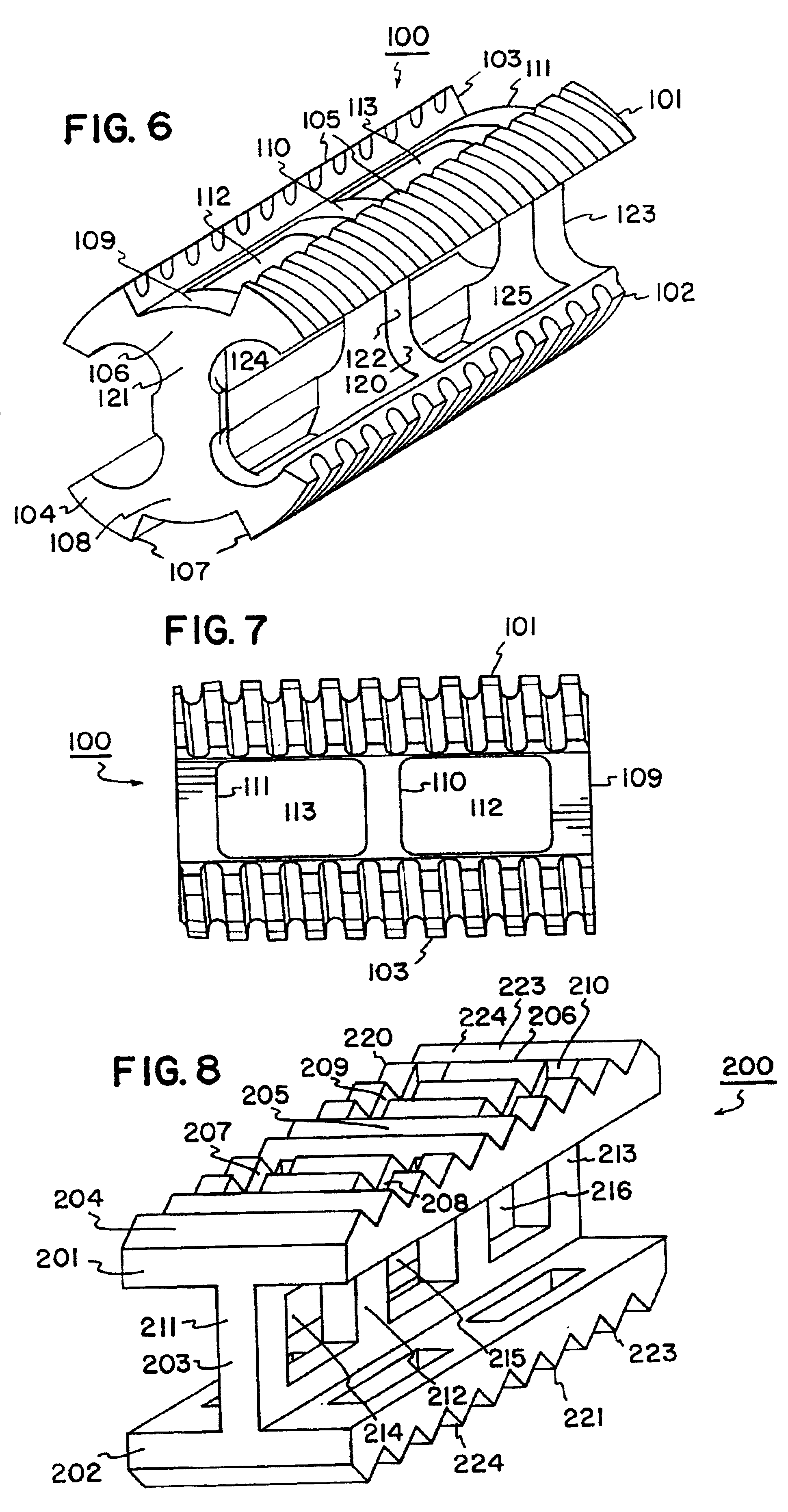
Referring now to FIGS. 6-7, an implant 100 is illustrated. The implant 100 includes four generally linear thread segments 101, 102, 103 and 104. Linear thread segments 101 and 103 provide a bearing surface 105 of a first transverse member 106 and linear thread segments 102 and 104 provide a bearing surface 107 of a second transverse member 108. As illustrated best in the top view of FIG. 7, thread segments 101 and 103 (and 102 and 104) are maintained in spaced apart alignment by transverse supports 109, 110 and 111. In the illustrated embodiment there are two openings 112 and 113 between transverse supports 109, 110 and 111. (The relative arrangement of the second transverse member 108 having thread segments 102 and 104 is identical to that just described for the first transverse segment 106). Transverse members 106 and 108 are maintained in spaced apart alignment by central support member 120. In the illustrated embodiment, central support member 120 comprises columns 121, 122 and ...

embodiment 100

The insertion tool 500, with threaded or unthreaded grips as just described, can also to include two additional grips that slide into the regions between thread segments 101 and 103 and 102 and 104 of implant embodiment 100. Such additional grips are illustrated, for example, in FIGS. 24, 27, 28 and 31 of co-assigned U.S. Pat. No. 5,609,636, the entire disclosure of which is incorporated herein by reference.


PUM


Abstract

The disclosure provides fusion implants, instruments and methods for insertion of the implants between opposing vertebral bodies to facilitate stabilization or arthrodesis of an intervertebral joint. A cross section through the longitudinal dimension of the implant is substantially configured in an “I” shape. In addition to other features, the implants of the invention provide a reduced contact surface area with the interior surface of a bore formed for receiving the implant.

Description

FIELD OF THE INVENTIONThis invention pertains to procedures for intervertebral stabilization. Specifically, the disclosure provides implants, instrumentation and methods to facilitate stabilization or fusion between two vertebrae.BACKGROUND OF THE INVENTIONChronic back problems cause pain and disability for a large segment of the population. Frequently, the cause of back pain is traceable to diseased disk material between opposing vertebrae. When the disk material is diseased, the opposing vertebrae may be inadequately supported, resulting in persistent pain.Surgical techniques have been developed to remove the diseased disk material and fuse the joint between opposing vertebral bodies. Stabilization and / or arthrodesis of the intervertebral joint can reduce the pain associated with movement of an intervertebral joint having diseased disk material. Generally, fusion techniques involve removal of the diseased disk and packing the void area with a suitable matrix for facilitating a bon...

Claims


Application Information

Patent Timeline
IPC IPC(8): A61F2/44A61F2/46A61F2/30A61F2/00A61F2/28
CPCA61F2/446A61F2/4611A61F2/447A61F2310/00023A61F2002/2817A61F2002/2835A61F2002/2839A61F2002/30166A61F2002/30179A61F2002/3023A61F2002/30403A61F2002/30777A61F2002/30785A61F2002/30789A61F2002/3085A61F2002/30858A61F2002/30874A61F2002/30904A61F2002/4475A61F2002/448A61F2220/0025A61F2230/0028A61F2230/0058A61F2230/0069A61F2310/00017A61F2002/30593A61F2002/30873
Inventor KOHRS, DOUGLAS W.
Owner ZIMMER SPINE INC
Why Eureka
Try Eureka