Osteointegrated implant systems

a technology of integrated implants and implants, applied in dental implants, dental surgery, medical science, etc., can solve the problems of high load on dental prosthetics and non-symmetric loading of threads/bone interfaces

Inactive Publication Date: 2007-12-13
ASUSTEK COMPUTER INC
View PDF8 Cites 15 Cited by
  • Summary
  • Abstract
  • Description
  • Claims
  • Application Information

AI Technical Summary

Benefits of technology

[0006]The present invention is embodied in a dental implant having a central body and having a long axis. The central body has an inserted end, an exterior end, an outer radius, an outer surface and a central receptacle for receiving a dental prosthesis. The central receptacle is located adjacent the exterior end. A plurality of helical threads are formed on at least a portion of the outer surface of the body. The threads are located such that the threads are symmetrical with respect to a plane through which the long axis extends, with the threads being formed such that each thread extends to a major thread radius greater than the outer radius. The threads each comprise a first feature and a second feature and a valley formed between the first feature and the second feature. The valley has a valley floor located at a floor radius, with the floor radius being greater than the outer radius of the body, and less than the major thread radius.

Problems solved by technology

Such dental prosthetics are subjected to high loads as a result of pressures generated while chewing.
It is known that the lack of a uniform stress distribution along the thread results from the fact that the joining pressures between the threads of the threaded body and the threaded portion into which the threaded body in reciprocal contact, which is limited inferiorly from the surface of the helicoids, do not present any symmetry with respect to the axis of the screw, not even if the engagement zone would results extended to an n number, although big, of gripping threads.
Presently, implant screws may evidence non-symmetric loading of the thread / bone interface that with time tends to deviate the original axis of the fixture within the bone.
The non-symmetric loading created by an osteointegrated implant having a single thread tends to distort the receiving bone site, thus resulting in the deviation.

Method used


Image

  • Osteointegrated implant systems
  • Osteointegrated implant systems
  • Osteointegrated implant systems

Examples


Embodiment Construction

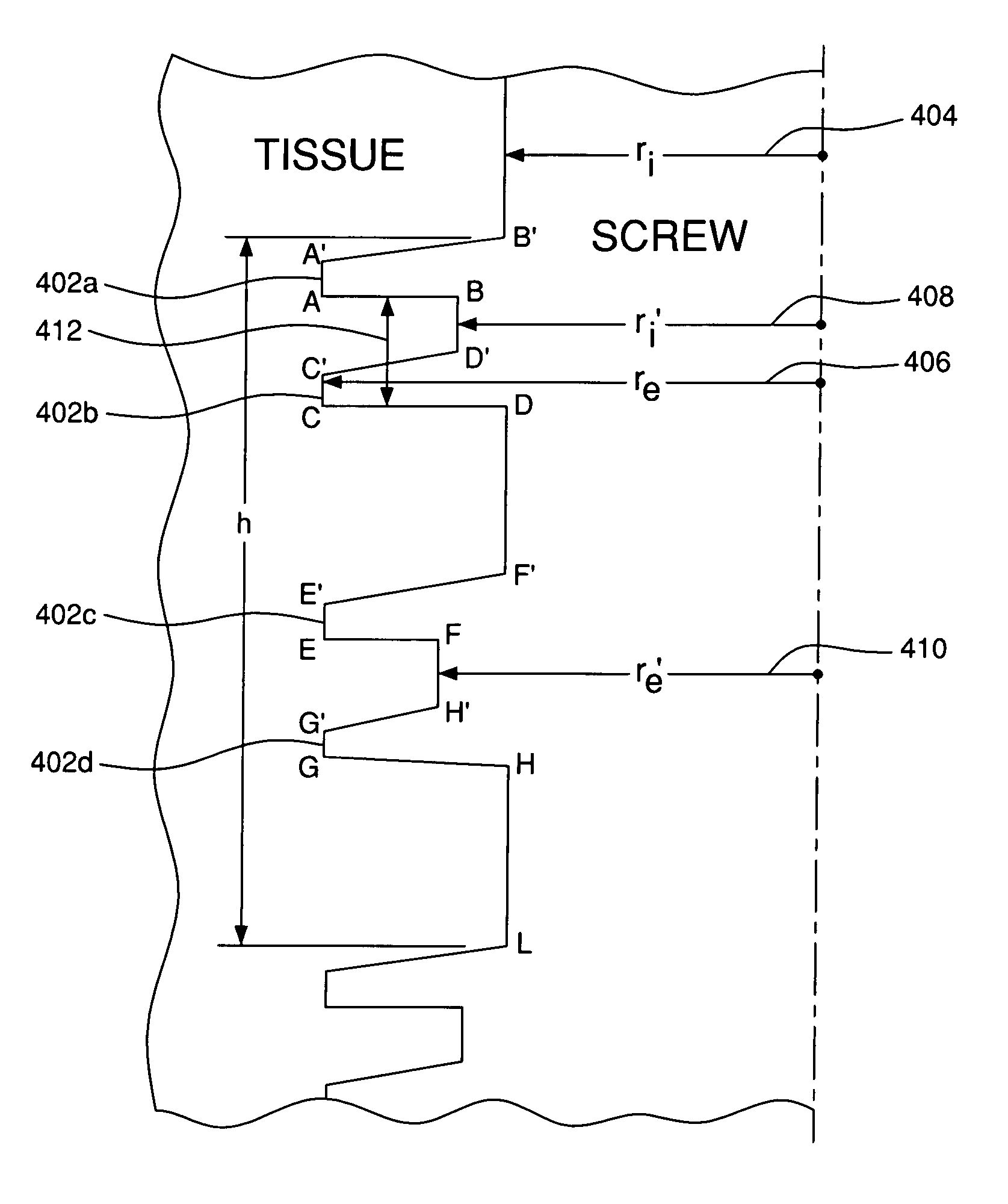
[0020]In order to provide a better understanding of the present invention, a discussion of the stresses inherent in a threaded dental implant is provided below. Further, the following conventions are provided:

[0021]ri=thread minor diameter

[0022]re=thread major diameter

[0023]Distribution of the Load on the Helicoids

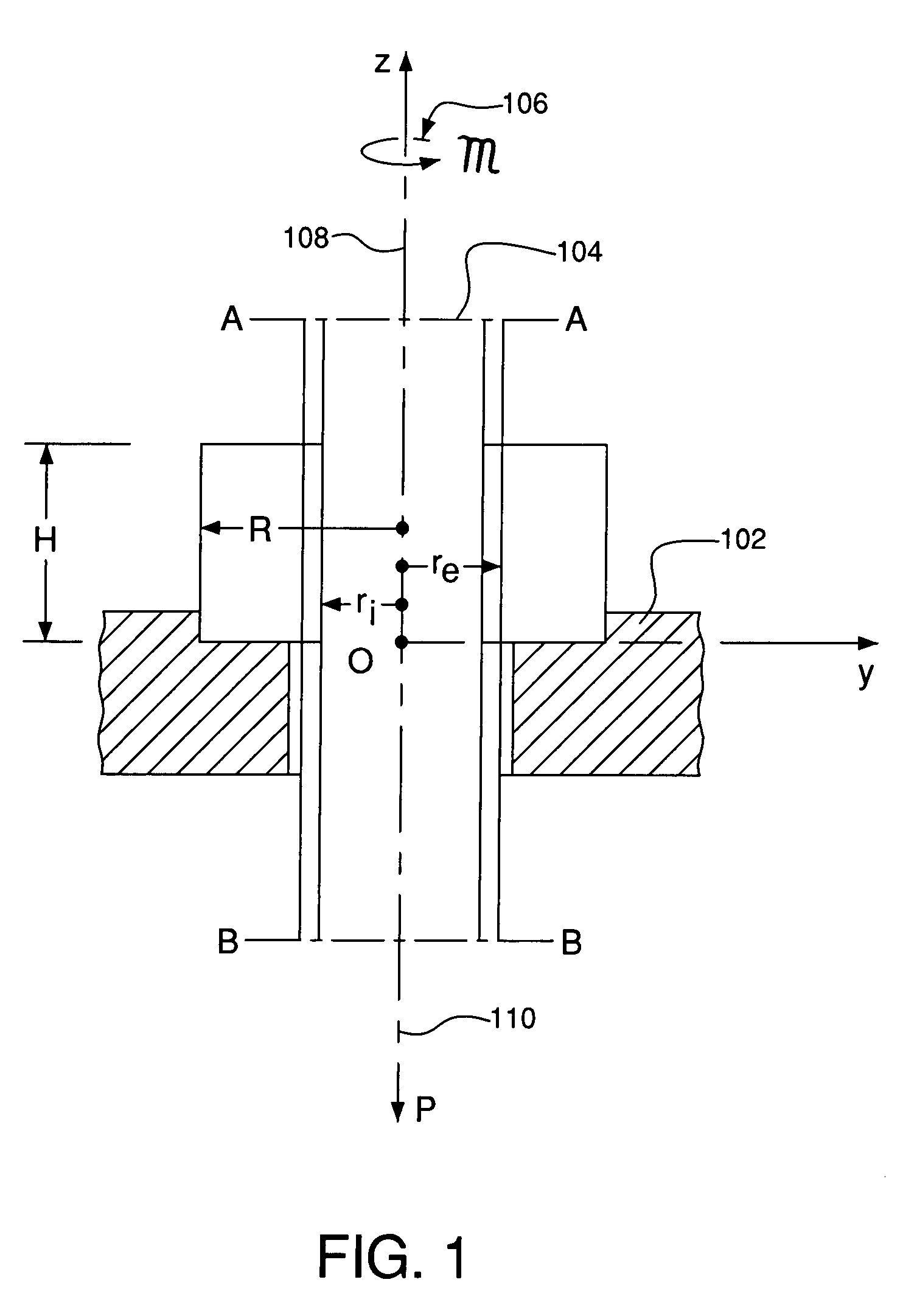
[0024]As shown in FIG. 1, the stresses and deformations within the implant may be considered by reference to a fixed nut 102 having an internally threaded bore within the nut and by a screw 104 (representing the implant) which is free to rotate. The screw may be subject to a twisting moment M 106 acting about the long axis of the screw, and to a load P 108 applied parallel to the long axis of the screw.

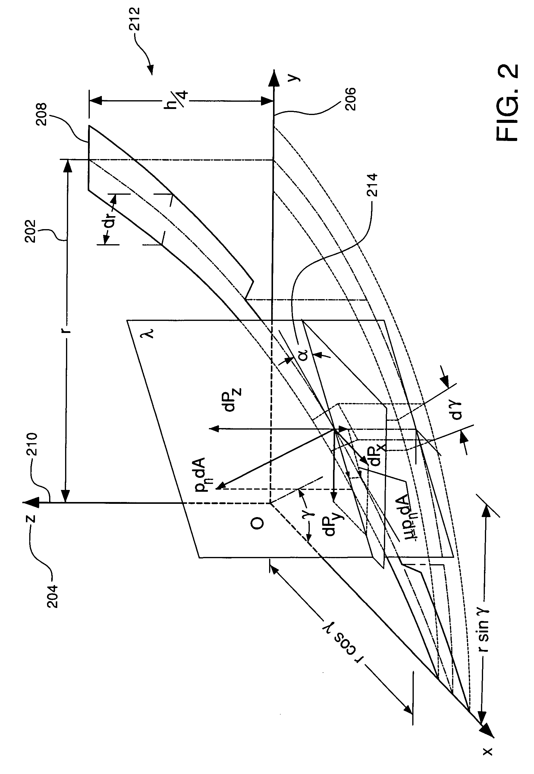
[0025]The thread formed on the screw may be modeled as a helix, as shown in FIG. 2. Coordinates r(202), z(204), and γ(206) may be used to define the location of the portion of the helix 208, wherein r is the radial distance from the center axis of the screw 210, and z is the...


PUM


Abstract

The present invention is a dental implant for affixing a dental prosthesis (mobile or fixed) to bone tissue to provide a stable integration of the implant with the bone tissue. The implant uses a multifaceted thread, which improves the distribution of loads from the implant to the bone tissue. The multifaceted thread may be of a tapered height adjacent an inserted end, such that the thread forms a self-threading implant, reducing the likelihood of tissue damage resultant from the use of multiple tools to form a thread in bone tissue prior to the insertion of the implant.

Description

BACKGROUND[0001]The present invention relates to the field of dental implants, and more particularly to osteointegrated dental implants utilizing a threaded body to integrate with bone tissue to provide a fixed mounting of the implant.[0002]Dental implants may be formed by integrating a threaded body into bone tissue to provide a structural foundation for dental prosthetics. Such dental prosthetics are subjected to high loads as a result of pressures generated while chewing. These pressures must be transferred to the underlying bone structure. As the underlying bone structure has material properties significantly different from the materials used for the implant, and as the bone tissue is itself living tissue, particular care must be used to control the transferring of loads from the implant to the bone tissue to minimize dislocation of the implant, as well as the potential of bone absorption.[0003]Typical implants utilize a common helical pair formed on the exterior surface of a st...

Claims


Application Information

Patent Timeline
Patent Type & Authority Applications(United States)
IPC IPC(8): A61C8/00
CPCA61C8/0022A61C8/0025
Inventor CLAUDIO, PIERPAOLOGODONO, FRANCESCOMARENZI, GAETANOSAMMARTINO, GILBERTO
Owner ASUSTEK COMPUTER INC
Why Eureka
Try Eureka