Gastrostomy Tube Extension Device

a technology of gastrostomy and tube extension, which is applied in the direction of trocar, catheter, infusion needle, etc., can solve the problems of large burden on the operator, damage to the abdominal part of the patient, etc., and achieve the effect of improving the ease of operation, facilitating further expansion, and facilitating modification of the narrowness of the gastrostomy tub

Active Publication Date: 2007-12-13
KPR U S LLC
View PDF16 Cites 14 Cited by
  • Summary
  • Abstract
  • Description
  • Claims
  • Application Information

AI Technical Summary

Benefits of technology

[0006] In order to solve the above-described problems, it is an object of the present invention to provide a gastrostomy tube extension device which can easily be inserted or taken out.

Problems solved by technology

However, in the gastrostomy tube described above, resistance of the stomach interior fixing member is significant and hence the removal is difficult, painful, and likely to cause damage to the abdominal part of the patient.
Complexity places a large burden on the operator.

Method used


Image

  • Gastrostomy Tube Extension Device
  • Gastrostomy Tube Extension Device
  • Gastrostomy Tube Extension Device

Examples


first embodiment

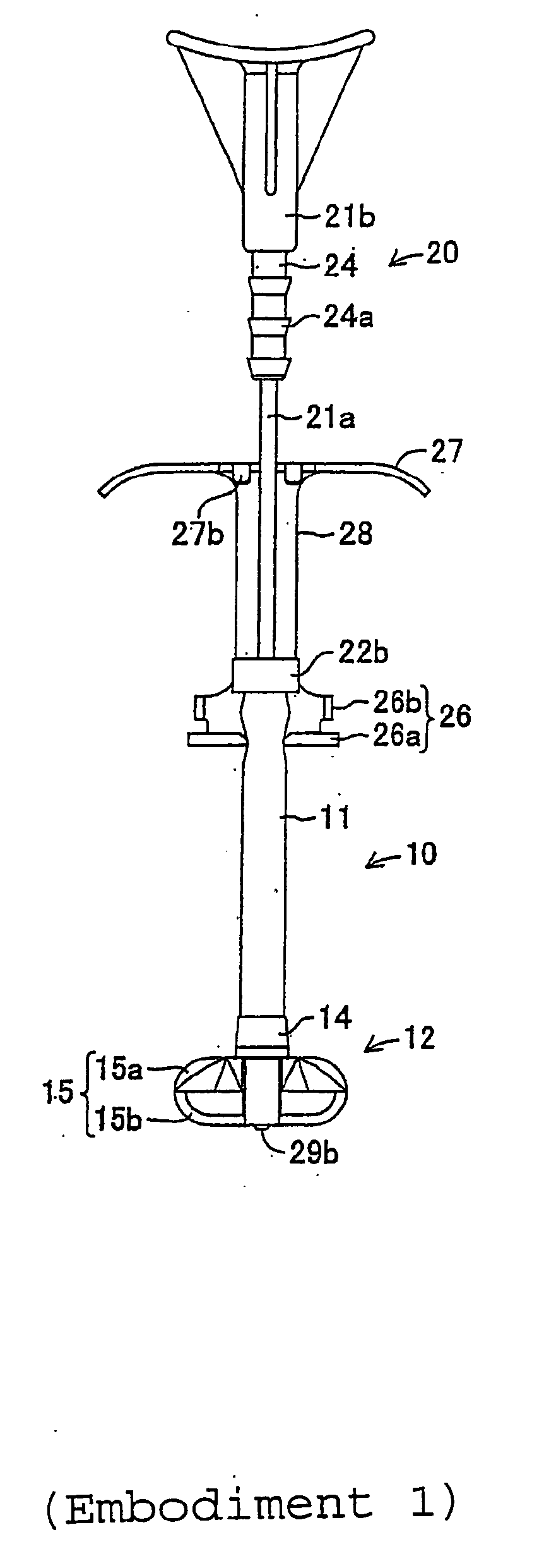
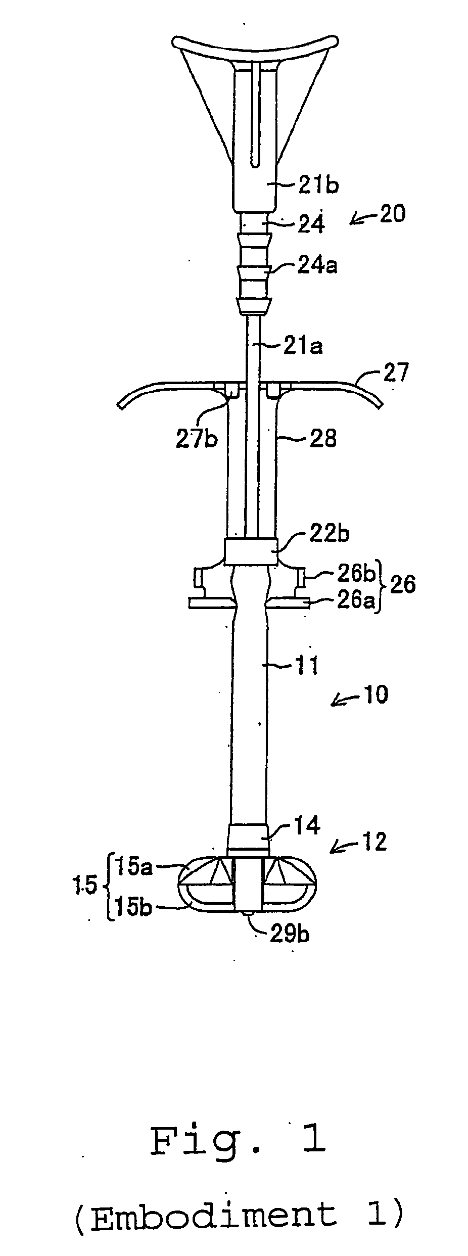
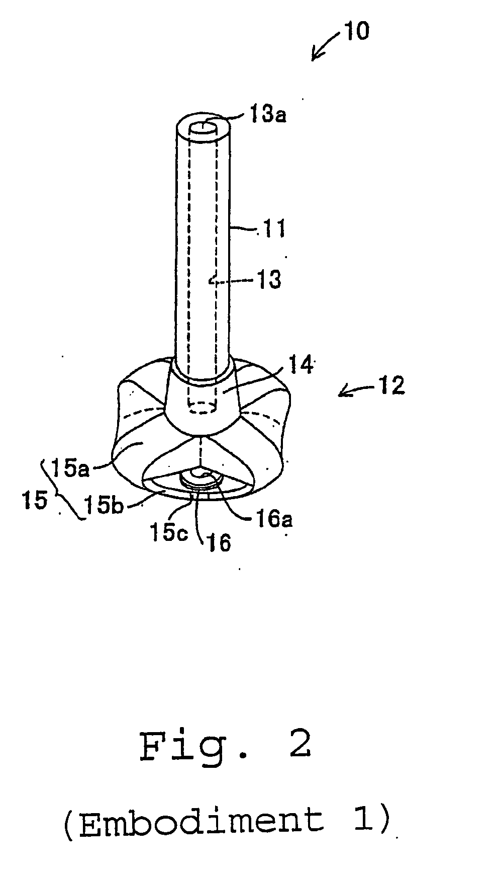
[0028] Referring to drawings 1 through 6, a first embodiment of the present invention will be described. FIG. 1 shows a state in which a gastrostomy tube extension device 20 according to the first embodiment of the present invention is mounted to a gastrostomy tube 10. The gastrostomy tube 10 includes a tube member 11 formed of polyurethane as shown in FIG. 2, and a stomach interior fixing member 12 connected to the lower end of the tube member 11. In the following description, the side of the tube member 11 is referred to as the upper side, and the side of the stomach interior fixing member 12 is referred to as the lower side.

[0029] The interior of the tube member 11 is formed into a feed path 13 of a hole for allowing fluid substances such as liquid food to pass through. The tube member 11 has elasticity, and hence is extended when pulled, and returns to its original state when the pulling force is removed. The tube member 11 has a function to block the hole by being fixed in the...

second embodiment

[0054]FIG. 7 through FIG. 9 show a gastrostomy tube extension device 30 according to a second embodiment of the present invention. A fixing member 32 provided on the gastrostomy tube extension device 30 includes an engaging projection 35 formed on the outer peripheral surface of the main body 32a at a position slightly lower than the center portion as shown in FIG. 9. The engaging projection 35 includes a tapered portion 35a, the diameter of which is smaller toward the distal end and gradually increases toward the proximal end, and a tapered portion 35b which is formed proximally to the tapered portion 35a so as to be vertically symmetric. Regarding the engaging member 33, the vertical length of a joint strip 38 is set to be longer than the engaging projection 35 of the fixing member 32 by a distance corresponding to the downward movement of the engaging projection 35 of the fixing member 32.

[0055] The structures of other portions of the gastrostomy tube extension device 30 are the...

third embodiment

[0056]FIG. 10 through FIG. 12 show a gastrostomy tube expansion device 40 according to a third embodiment of the present invention. In a rod 41 provided on the gastrostomy tube extension device 40, an engaging stepped portion 44a is formed of a ring-shaped projection formed on the outer peripheral surface of a cylindrical portion 44 having a semi-circular vertical cross-section, and five of those projections are formed along the axis of the cylindrical portion 44 at regular intervals.

[0057] As shown in FIG. 12, a fixing portion 42 is formed of a cylindrical member the diameter of which is set to be larger toward the lower edge, and gradually decreases toward the upper portion thereof, and is fixed to the outer peripheral surface of the tube member 11 of the gastrostomy tube 10 at the upper end portion thereof. The lower surface of the fixing portion 42 constitutes an engaging projection 45. A lower engaging portion 46 of an engaging member 43 is constituted of the frame body includ...


PUM


Abstract

To provide a gastrostomy tube extension device which can facilitate the insertion or removal operation in and from the patient, as well as to increase the simplicity of manufacture without sacrificing safety of operation. [Solving Means] A gastrostomy tube extension device 20 used for inserting or taking out the gastrostomy tube 10 into / from the hole on the patient includes a rod 21, a fixing member 22, and an engaging member 23. The rod 21 is formed of a rod-shaped member, and is formed with engaging stepped portions 24a on the proximal portion thereof. The fixing member 22 is adapted to be capable of moving along the longitudinal direction of the rod 21, and an engaging projection 35 which can be fixed to the tube member 11 is formed on the peripheral surface of the fixing member 22. The engaging member 23 includes a lower engaging portion 26 engageable with the engaging projection 35 and an upper engaging portion 27 which is engageable with the engaging stepped portion 24a. This assembly allows the extension to be locked, allowing the operator to manipulate the device with a single hand.

Description

TECHNICAL FIELD [0001] The present invention relates to a gastrostomy tube extension device for inserting or removing a gastrostomy tube used for feeding fluid substances such as liquid food into a stomach of a patient into / from the patient' body. BACKGROUND ART [0002] Hitherto, feeding of the fluid substances such as the liquid food or nutrient preparation using the gastrostomy tube has been carried out for persons whose capability to take food orally by their own abilities is deteriorated due to aging or diseases (hereinafter referred to as a “patient”). The gastrostomy tube includes a stomach interior fixing member to be installed on the inside of a stomach wall at a hole (a gastric fistula) for dietary intake formed on the abdomen of the patient, and a tube member connected to the stomach interior fixing member at the distal portion thereof and extends through the hole toward the outside of the patient at the proximal portion. When inserting the gastrostomy tube into the hole fo...

Claims


Application Information

Patent Timeline
Patent Type & Authority Applications(United States)
IPC IPC(8): A61M25/01A61B17/34A61J15/00A61M25/02A61M25/04A61M25/06
CPCA61B17/3415A61J15/0015A61J15/0038A61J15/0057A61M25/0662A61J15/0026A61M25/04A61J15/00A61M25/02A61B17/34
Inventor WATANABE, MOTONORIABE, KAZUHIRONAGATA, KATSUKI
Owner KPR U S LLC
Why Eureka
Try Eureka