Visual indicator for electrosurgical instrument fields

Inactive Publication Date: 2007-12-13
TOLMEI RON
View PDF3 Cites 17 Cited by
  • Summary
  • Abstract
  • Description
  • Claims
  • Application Information

AI Technical Summary

Benefits of technology

[0016]Accordingly with the major aspects of the problem, already briefly recited, the present invention is a means to visually annunciate when an electrosurgical instrument is active. This is to alert the operating surgeon, and observing personnel, that the device

Problems solved by technology

Unfortunately these failures, if annunciated at all, are annunciated only on the remotely located generator and owing to background noise in the operating suite often not heard or seen by the surgeon.
These self activating failures can and have caused patients to experience severe burns and in at least one occasion loss of an infant's toes during delivery.
This trial and error approach causes unnecessary lesions in the patient.
This has proved difficult because traditionally there is more than one surgeon attending the patient at any one time.
Additionally, out of necessity the surgeons are located on opposite sides of the patient making it difficult to have a central location for the handpiece.
Unfortunately the

Method used


Image

  • Visual indicator for electrosurgical instrument fields
  • Visual indicator for electrosurgical instrument fields
  • Visual indicator for electrosurgical instrument fields

Examples


Example

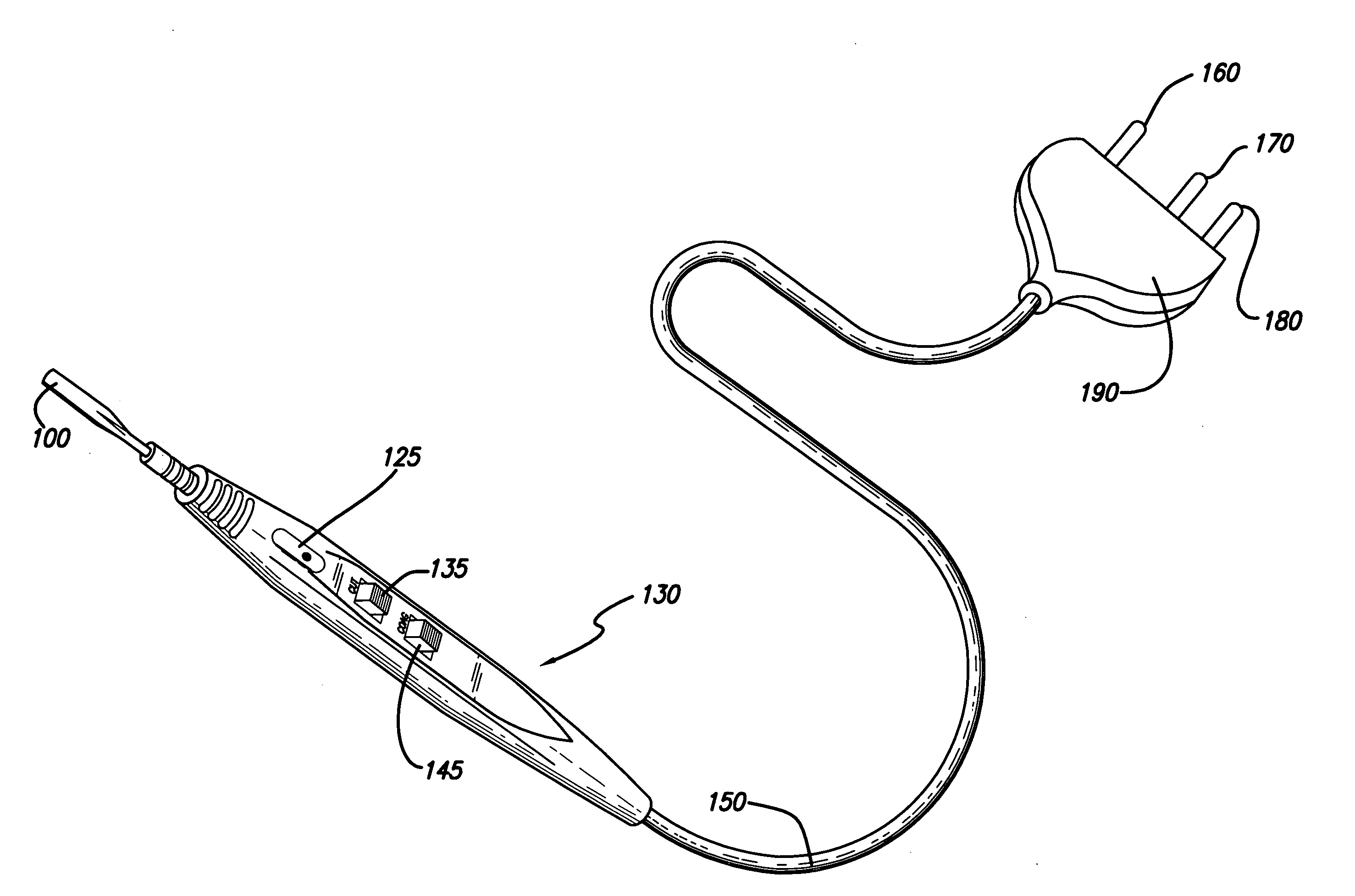
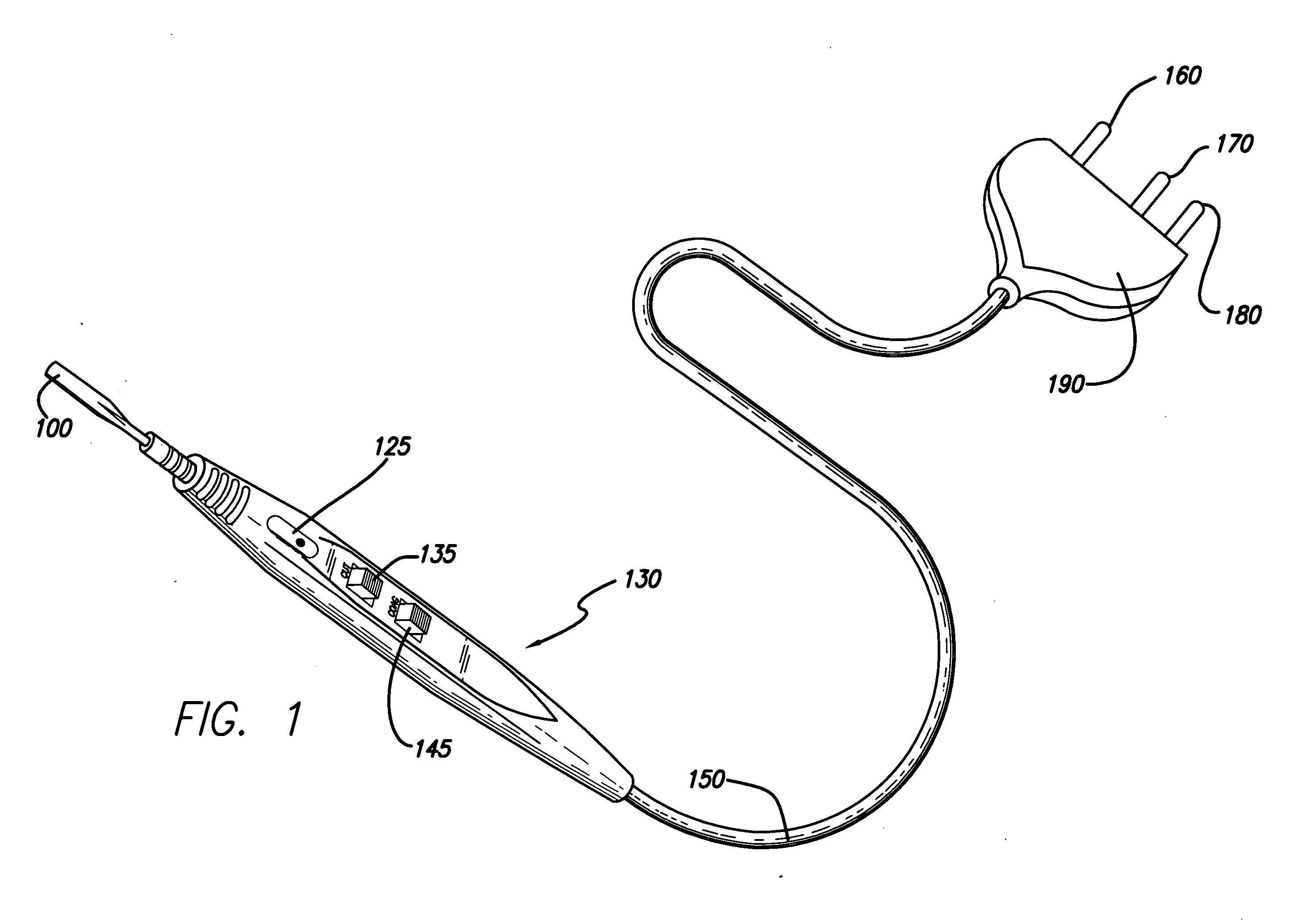
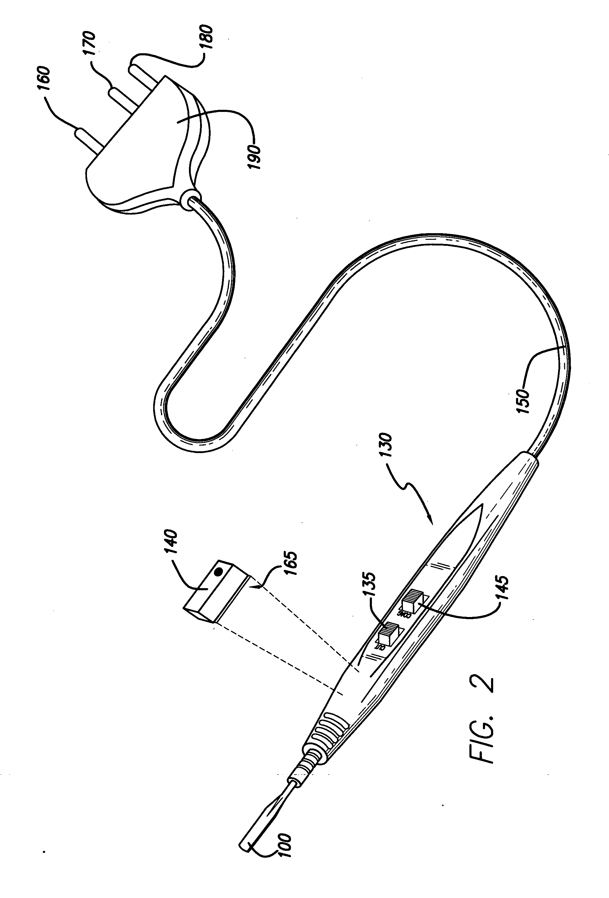
[0027]The present invention is a means to visually annunciate when an electrosurgical instrument is active by detecting the accompanying electric field and ionizing a gas filled lamp. This visual indication alerts surgeons, and bystanders, that the device is operational thereby mitigating the possibility of injuring a patient. The device is comprised of an electrically insulated enclosure filled with a gas in close proximity, but without electrical contact, to a surgical handpiece connected by cable to a radio frequency current generator.

[0028]Currently electrosurgical equipment have visual and audible annunciation when active but only on the radio frequency current generator that is usually located some distance away from the patients bed side. This makes it difficult to see or hear annunciations especially during procedures that require intense concentration.

[0029]This invention provides a visible indication that the device is active on the handpiece where the surgeon's attention ...


PUM


Abstract

A device to visually indicate the presence of electric fields in electrosurgical apparatus, without the necessity of wiring or an electrical connection to the apparatus, to visually annunciate when an electrosurgical instrument is active is disclosed. This is to alert the operating surgeon, and observing personnel, that the device is operational to mitigate the possibility of anyone inadvertently being injured. The device is comprised of an electrically insulated enclosure filled with a gas in close proximity to a surgical handpiece connected to a radio frequency current generator.

Description

CROSS-REFERENCE TO RELATED APPLICATIONS[0001]References Cited[0002]U.S. Patent Documents4,112,950Sep. 12, 1978Pike606 / 424,170,234Oct. 9, 1979Graham606 / 424,202,337May 13, 1980Hren, et al.606 / 484,347,842Sep. 7, 1982Beale604 / 204,427,006Jan. 24, 1984Nottke606 / 424,443,935Apr. 24, 1984Zamba, et al.29 / 6224,545,375Oct. 8, 1985Cline606 / 42.5,817,091Oct. 6, 1998Nardella et al.606 / 38.6,242,741Jun. 5, 2001Eric Miller et al.250 / 3636,402,741Jun. 11, 2002Keppel et al.606 / 346,534,770Mar. 18, 2003Miller et al.250 / 3636,676,660Jan. 13, 2004Wampler et al.606 / 516,685,701Feb. 3, 2004Orszulak et al.606 / 346,984,826Jan. 10, 2006Miller et al.250 / 3637,041,096May 9, 2006Malis et al.606 / 32BACKGROUND OF THE INVENTION[0003]1. Field of the Invention[0004]The present invention relates to cost-effective and readily realizable means to reduce the possibility of unintentionally cutting or cauterizing a patient, or new born, in proximately of an electrosurgical handpiece.[0005]2. Discussion of Background[0006]The first ...

Claims


Application Information

Patent Timeline
IPC IPC(8): A61B18/14
CPCA61B18/14A61B2019/4836A61B18/1402Y10S128/908A61B2090/0807
Inventor TOLMEI, RON
Owner TOLMEI RON
Why Eureka
Try Eureka