Vertebral fixation device and tool for assembling the device
- Summary
- Abstract
- Description
- Claims
- Application Information
AI Technical Summary
Benefits of technology
Problems solved by technology
Method used
Image

Examples
Embodiment Construction
[0014]The vertebral fixation device proposed in this invention is intended to provide a satisfactory solution to the aforementioned problems.
[0015]Two devices shall be described, one of which will be a vertebral fixation device to immobilise the vertebrates in all kinds of cases (deviations, depth, fractures . . . ) and another vertebral fixation device that we shall refer to as a lateral connector to correct more serious lateral deviations of the vertebrates.
[0016]First of all, the main vertebral fixation device will be described, followed by the tool used to assemble this fixation device and finally, the lateral connector will be described.
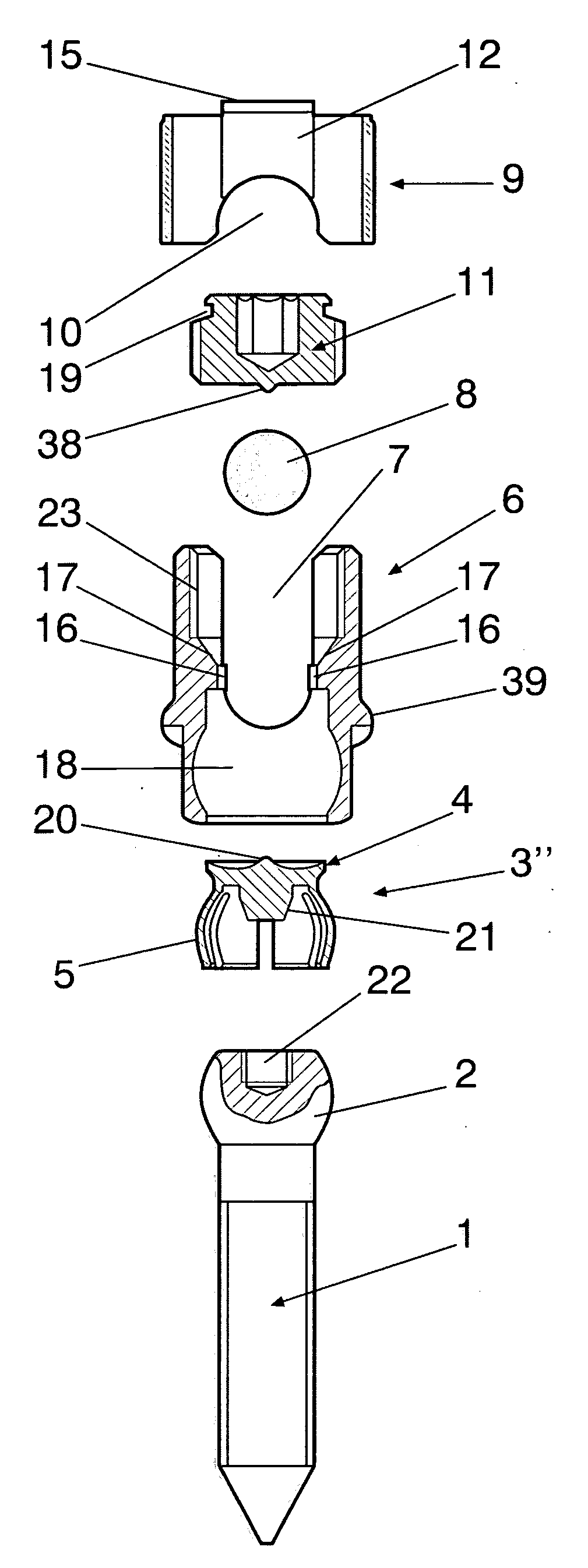
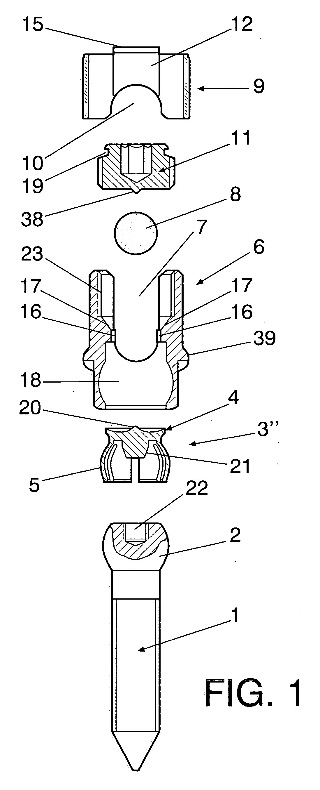
[0017]The fixation device basically consists of a pedicle screw with a partially spherical head, a flexible rosette that presses on and fixes the position of the head at a particular angle, a tulip that has two lateral notches opposite each other and a cavity that holds the rosette, a bar that constitutes the connection with other devices fixed ...
PUM
 Abstract
Description
Claims
Application Information
 - R&D
- Intellectual Property
- Life Sciences
- Materials
- Tech Scout
- Unparalleled Data Quality
- Higher Quality Content
- 60% Fewer Hallucinations
Browse by: Latest US Patents, China's latest patents, Technical Efficacy Thesaurus, Application Domain, Technology Topic, Popular Technical Reports.
© 2025 PatSnap. All rights reserved.Legal|Privacy policy|Modern Slavery Act Transparency Statement|Sitemap|About US| Contact US: help@patsnap.com