Source Separator for Power over Ethernet Systems

a source separator and ethernet technology, applied in the field of power over ethernet, can solve the problems of high cost of installation of such cables, high cost of installing such additional cables, and high cost of poe hub,

Inactive Publication Date: 2007-12-13
ROBBINS STEVEN ANDREW
View PDF9 Cites 42 Cited by
  • Summary
  • Abstract
  • Description
  • Claims
  • Application Information

AI Technical Summary

Benefits of technology

[0007]Accordingly, it is a principal objective of the present invention is to overcome the major disadvantages of prior art by providing an inexpensive and efficient means to power two PD's over a single network cable. The invention includes a method and an apparatus, each with several embodiments, described below.

Problems solved by technology

Network cables radiate out from the PSE to all the PD's in the building, often running long distances through plenums, and sometime passing through walls or floors; installing such cables often requires electricians or other trained professionals, sometimes at considerable expense.
A user who wishes to have a second PD in his office would normally need to run a second network cable through the building; the problem is that the cost of installing this additional cable can easily exceed the cost of the PD itself.
The biggest disadvantages of the PoE hub are cost and efficiency.
The PoE hub is expensive because it must contain a lot of complex circuitry, including a power supply large enough to run all the external PD's.
A significant portion of the power from the remote PSE is wasted in the conversion process and to power the PoE hub's internal circuitry, thus making the PoE hub inefficient.

Method used


Image

  • Source Separator for Power over Ethernet Systems
  • Source Separator for Power over Ethernet Systems
  • Source Separator for Power over Ethernet Systems

Examples


Embodiment Construction

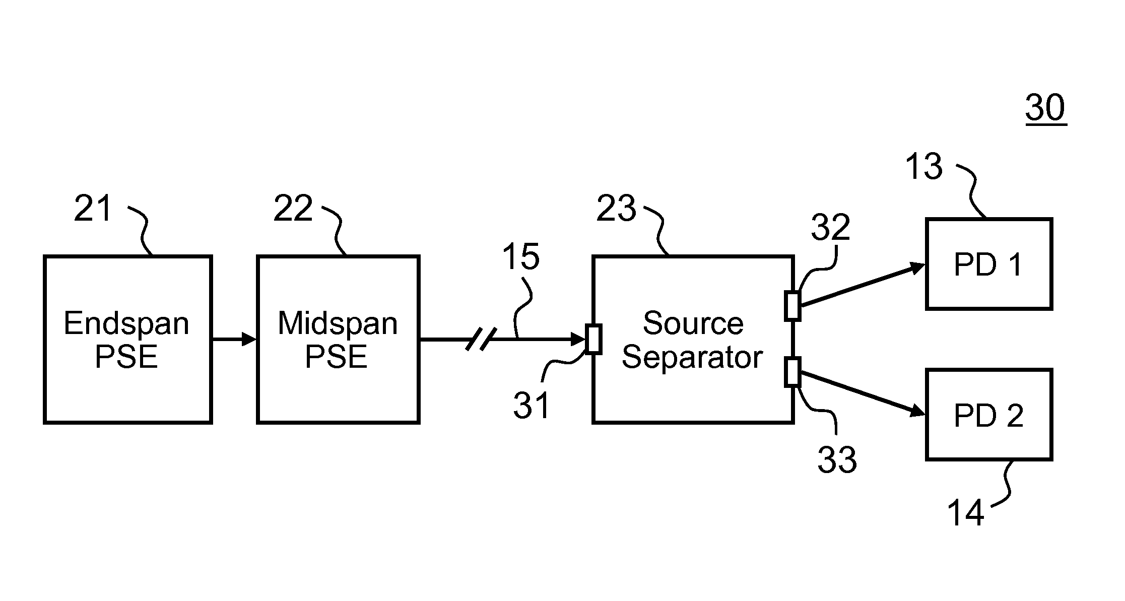
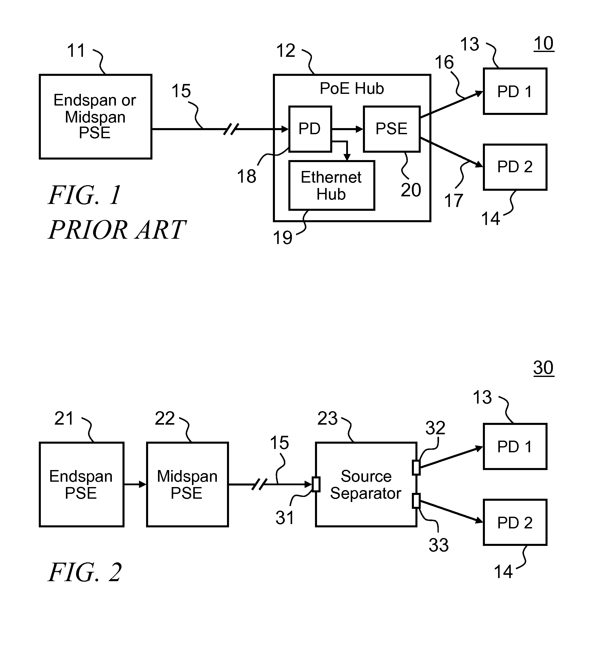
[0020]FIG. 2 depicts a novel system 30 in accordance with the teachings of the invention. Network cable 15 carries power from both PSE'S: the endspan PSE 21 sources power on two of the twisted-pairs within 15; and the midspan PSE 22 sources power on the other two twisted-pairs within 15. The source separator apparatus 23 separates power from the two sources: the endspan PSE 21 powers the first PD 13; and the midspan PSE 22 powers the second PD 14.

[0021]Some major advantages of the present invention over the prior art are lower cost, and higher efficiency. The cost is lower because the source separator 23 doesn't require an internal PD or PSE, or the associated circuitry such as a DC / DC converter to provide isolation and maintain voltage regulation. Efficiency is improved because power from the endspan PSE 21 and midspan PSE 22 pass directly through the source separator 23 without conversion.

[0022]The present invention meets a significant technical challenge: the source separator mus...


PUM


Abstract

A method and apparatus with several embodiments for separating power supplied by two Power Sourcing Equipment (P SE) for Power over Ethernet (PoE) systems, for the purpose of providing power to a two separate Powered Devices (PD) over a single network cable. A first PD runs off power supplied by an endspan PSE, and a second PD runs off power supplied by a midspan PSE. An Ethernet hub, switch, or repeater circuit is also included to allow both PD's to communicate with the endspan PSE.

Description

CROSS- REFERENCE TO RELATED APPLICATIONS[0001]This application claims priority from US Provisional Patent Application number 60804215 titled A Passive Separator for PoE Power Sources filed on Jun. 8, 2006.TECHNICAL FIELD OF THE INVENTION[0002]The invention relates generally to the field of Power over Ethernet (PoE): a system that provides power over computer networking cables.BACKGROUND OF THE INVENTION[0003]The IEEE issued an amendment to IEEE Std 802.3™-2002; this amendment, titled Data Terminal Equipment (DTE) Power via Media Dependent Interface (MDI), was published as IEEE Std 802.3af™-2003, and is hereinafter referred to as the “IEEE standard”. The IEEE standard, whose contents are incorporated herein by reference, is commonly referred to as Power over Ethernet (PoE), and specifies methods and requirements for delivery of limited DC power using two of the four twisted-pairs contained within standard Ethernet cables. Equipment that supplies power on Ethernet cables are called Po...

Claims


Application Information

Patent Timeline
Patent Type & Authority Applications(United States)
IPC IPC(8): G06F1/26
CPCH04L2012/445H04L12/10
Inventor ROBBINS, STEVEN ANDREW
Owner ROBBINS STEVEN ANDREW
Why Eureka
Try Eureka