Power system and work machine using same

a technology of power system and work machine, applied in the direction of fluid coupling, servomotor, coupling, etc., can solve the problems of low energy recovery rate, unfavorable energy recovery, and unsatisfactory energy recovery effect,

Inactive Publication Date: 2005-09-20
CATEPILLAR SARL +1
View PDF15 Cites 37 Cited by
  • Summary
  • Abstract
  • Description
  • Claims
  • Application Information

AI Technical Summary

Benefits of technology

[0024]The present invention is advantageous because the power system 14 including the battery 40, the capacitor 39 and the variable displacement hydraulic motor 35 is a relatively inexpensive and efficient alternative to the diesel engine. By removing the diesel engine from the power system, undesirable emissions, such as CO2 and NOx, which are major factors in global warming and air pollution, are reduced, if not eliminated. Further, the noise and vibrations produced by the power system 14 are also reduced. Moreover, by directing the flow of hydraulic fluid from the first fluid volume 23 during plunger 19 retraction through the variable displacement hydraulic motor 35, the power system 14 can be powered by an unthrottled hydraulic flow passing therethrough towards the tank line 46. Thus, by replacing a throttle valve that regulates the flow of fluid from the larger cross-section 23a of the first fluid volume 23 during plunger 19 retraction with the variable displacement motor 35, the efficiency of the power system 14 is increased.

Problems solved by technology

Despite various improvements made over the years to the diesel engines, diesel engines still remain not only a source of vibration and noise, but also undesirable emissions, such as carbon dioxide (CO2), nitrogen oxides (NOx), unburned hydrocarbons and soot.
Because of the significant amount of high pressure hydraulic flow being bled from the power system, the rate of energy recovery is too low to be efficient.
In addition, the energy recovery only occurs when the plunger is retracting within the cylinder, thereby further reducing the efficiency of the energy recovery.
Thus, some of the hydraulic power of the flow is wasted, rather than used to power the generator.
Moreover, fuel cells, hydrogen absorbing alloys cells and reformers can be relatively expensive and problematic.

Method used


Image

  • Power system and work machine using same
  • Power system and work machine using same
  • Power system and work machine using same

Examples


Embodiment Construction

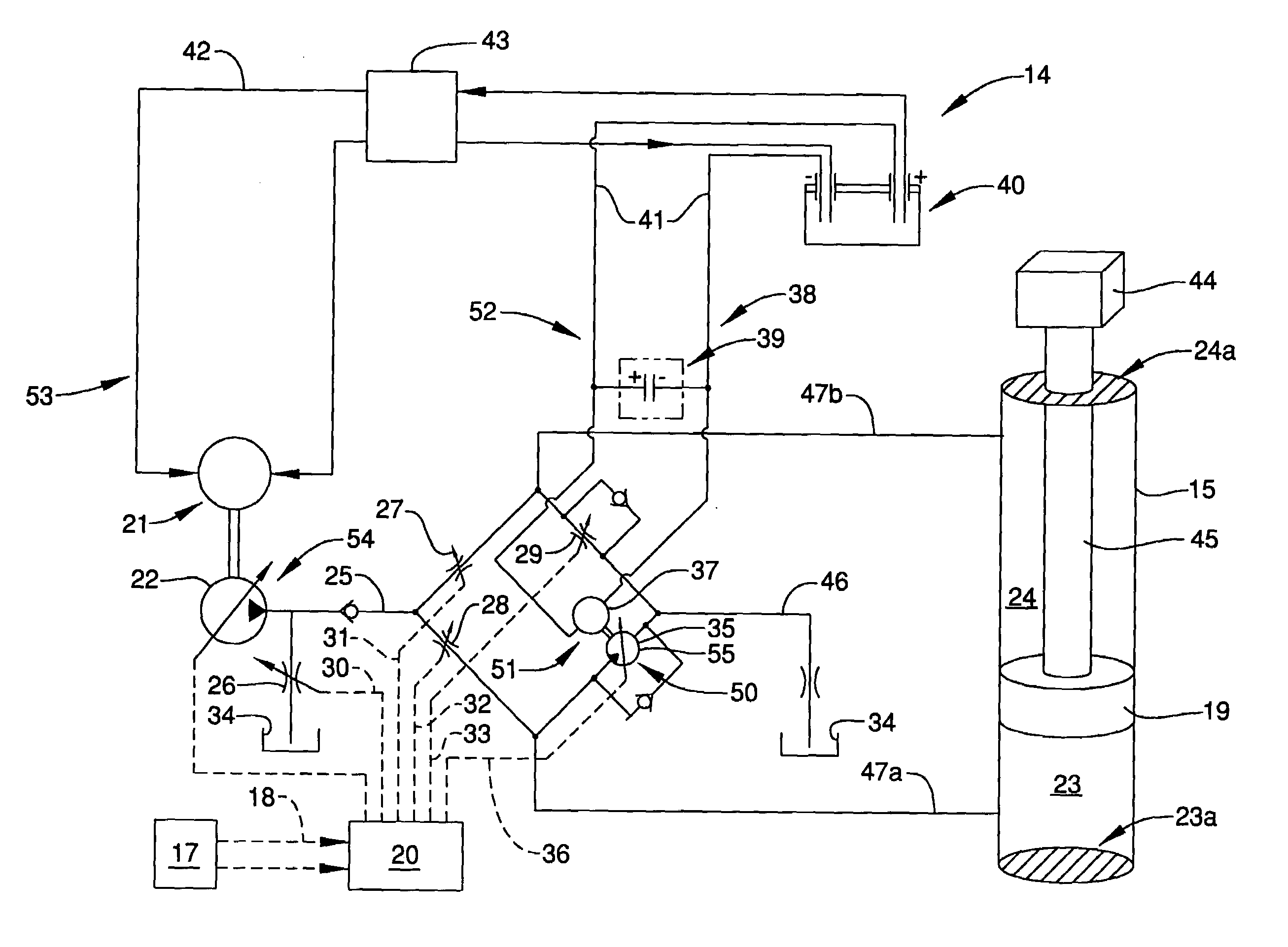
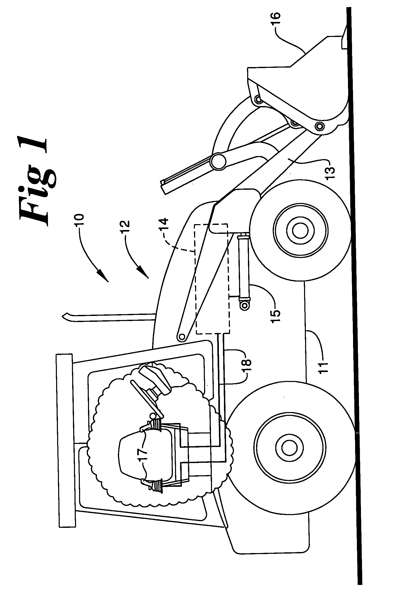
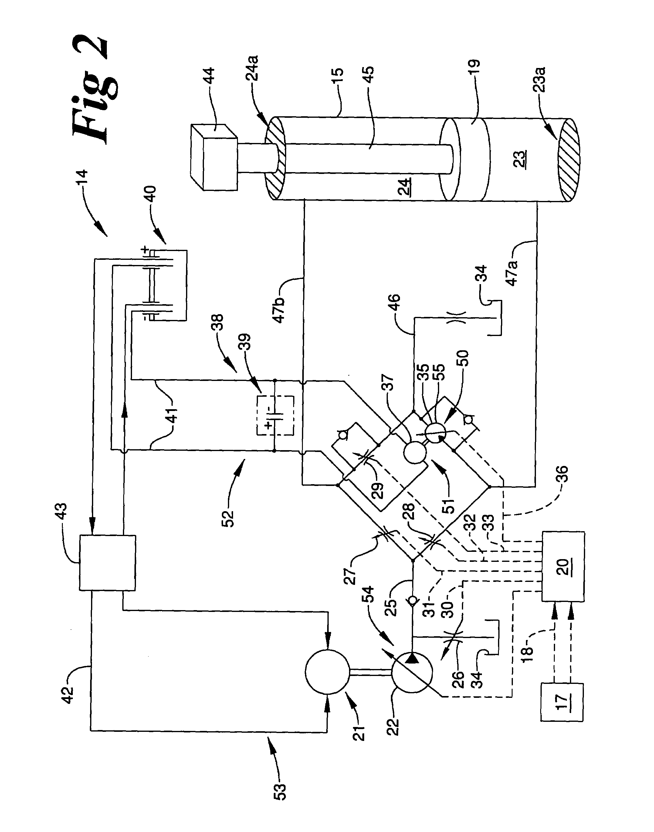
[0012]Referring to FIG. 1, there is shown a side view of a work machine 10. The work machine 10 includes a work machine body 111 to which an implement is attached. Although the work machine 10 is illustrated as a loader 12, it should be appreciated that the present invention is applicable to work machines including any type of hydraulically controlled implement. In addition, the present invention is applicable to work machines including more than one implement. Moreover, the present invention is applicable to power systems used to power apparatuses other than implements, and / or within vehicles other than construction work machines.

[0013]The loader 12 is controlled with implement controls 17. Although the work machine 10 includes the implement controls 17 being attached to an arm of the operator's seat, those skilled in the art will appreciate that the implement controls 17 can be positioned at any point within an operator's control station that is within the operator's reach. The im...


PUM


Abstract

In the present invention, a power system includes at least one hydraulic cylinder that defines a first fluid volume and a second fluid volume separated from one another via a moveable plunger. Hydraulic power created within the hydraulic cylinder is converted to mechanical power by a fluid driven rotating device that is fluidly connected to at least the first fluid volume. A generator is attached to the fluid-driven rotating device, and produces electrical power that is stored in a power storage system including at least one of a battery and a capacitor. The stored electrical power can be supplied to an electric motor that is operable to power a hydraulic pump. The hydraulic pump supplies hydraulic fluid to the hydraulic cylinder. The power system of the present invention is a relatively inexpensive and efficient alternative to a power system including a diesel engine that can be a source of undesirable emissions, noise and vibrations.

Description

TECHNICAL FIELD[0001]The present invention relates generally to power systems, and more specifically to a power system that is capable of recovering energy within a work machine.BACKGROUND[0002]Diesel engines are often used to power various types of work machines. Despite various improvements made over the years to the diesel engines, diesel engines still remain not only a source of vibration and noise, but also undesirable emissions, such as carbon dioxide (CO2), nitrogen oxides (NOx), unburned hydrocarbons and soot. All of these have been found to contribute to global warming and air pollution.[0003]Over the years, engineers have attempted to decrease the use of diesel engines in order to decrease undesirable emissions, along with noise and vibrations. For instance, work machines often use a diesel engine to power a hydraulic pump that delivers hydraulic fluid to a hydraulic cylinder. Movement of a weight-driven plunger within the hydraulic cylinder drives the movement of the work...

Claims


Application Information

Patent Timeline
Patent Type & Authority Patents(United States)
IPC IPC(8): F15B11/024F15B21/14
CPCF15B11/024F15B21/14F15B2211/20515F15B2211/20546F15B2211/214F15B2211/30575F15B2211/31576F15B2211/327F15B2211/35F15B2211/40515F15B2211/41563F15B2211/426F15B2211/45F15B2211/6303F15B2211/6346F15B2211/6652F15B2211/6654F15B2211/7053F15B2211/7058F15B2211/88E02F9/2217E02F9/2091E02F9/2095
Inventor YOSHINO, KAZUNORI
Owner CATEPILLAR SARL
Why Eureka
Try Eureka