
Sprinkler Mount

a technology of sprinkler and mount, which is applied in the field of sprinkler mount, can solve problems such as difficulty in access, and achieve the effect of simple and cost-effective construction

Inactive Publication Date: 2007-12-20
WITZENMANN GMBH
View PDF9 Cites 9 Cited by
  • Summary
  • Abstract
  • Description
  • Claims
  • Application Information

AI Technical Summary

Benefits of technology

The present invention provides a sprinkler mount that is simple and cost-effective to install. The mount can be easily attached to different types of ceiling girders and is convenient to handle and install. It is designed to be easily attached to a sprinkler nozzle and is connected to a fire extinguishing system through a flexible hose line. The mount includes a bridge member that is connected to the ceiling system and a detachable clamp that fixes the bridge and the girder to the ceiling system. The clamp is designed to enclose both the bridge and the girder, ensuring a secure and effective attachment. The invention also provides a device for attaching a sprinkler nozzle to the mount, which includes a sleeve and a clamp that fixes the nozzle to the mount. The fastener used in the clamp is designed to ensure a secure and effective attachment. Overall, the invention provides a simple and cost-effective solution for attaching a sprinkler mount to a fire extinguishing system.

Problems solved by technology

While the rectangular tube of US 2002 / 066834 has advantages in relation to the above folded sheet-metal blank for use as a bridge, because it is more stable, torsion resistant, and cost-effective, the disadvantages of the subject matter of US-A-2002 / 066834 are that the clamp must ensure the mutual fixing of bridge and girder via two or even three fasteners.
This is disadvantageous above all if the position of the bridge must be changed or the bridge must even be removed entirely on location when the suspended ceiling system has already been mounted, because between two and six fasteners must be loosened for this purpose and subsequently tightened again.
In addition, when the bridge is mounted, some of the fasteners are even covered by the girder or bridge and are thus difficult to access.
Further disadvantages exist in the subject matter of DE-A-197 09 916 because the mount may only be used with those girders which have the desired slotted recesses.

Method used


Image

  • Sprinkler Mount
  • Sprinkler Mount
  • Sprinkler Mount

Examples


Embodiment Construction

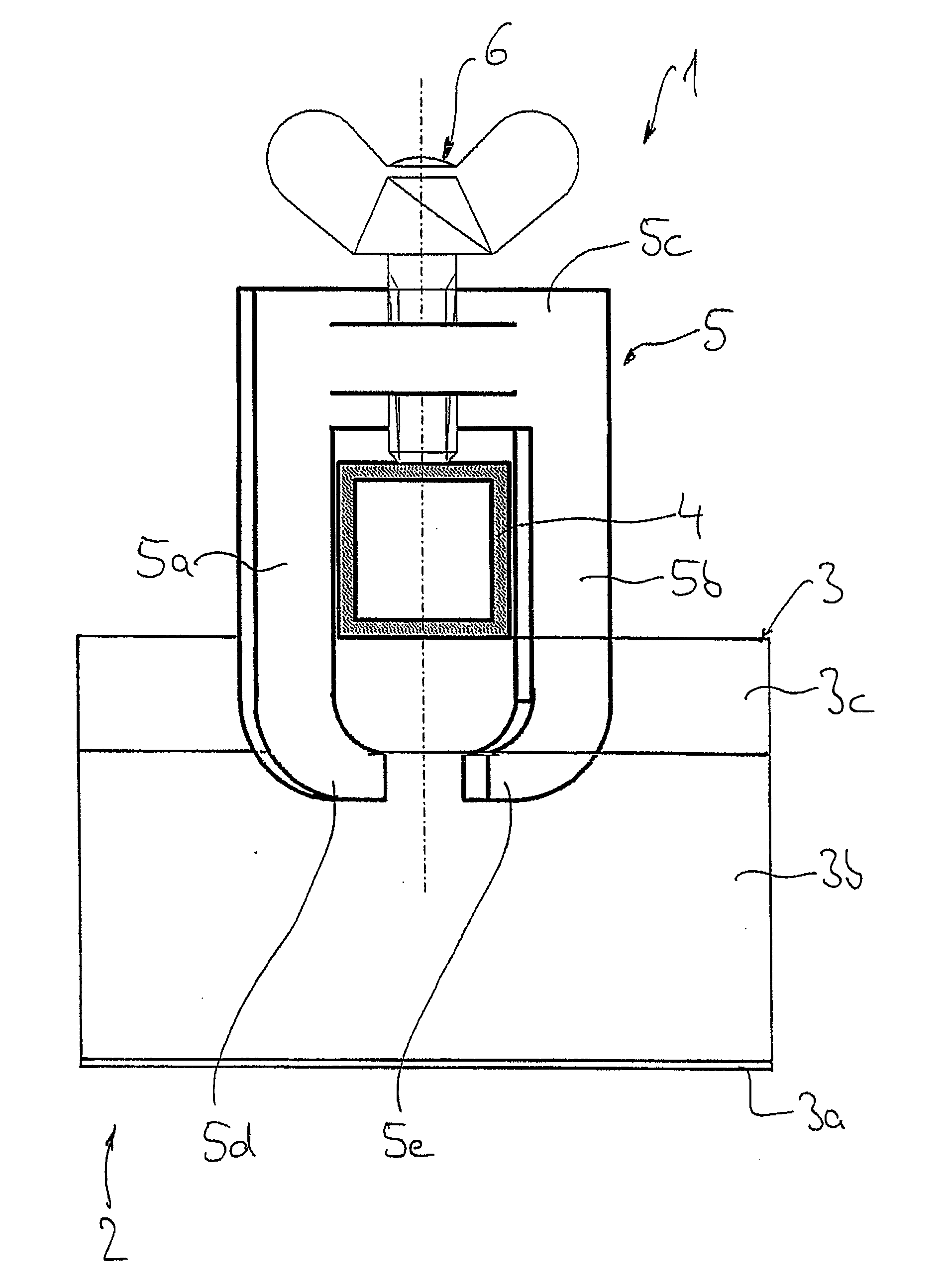
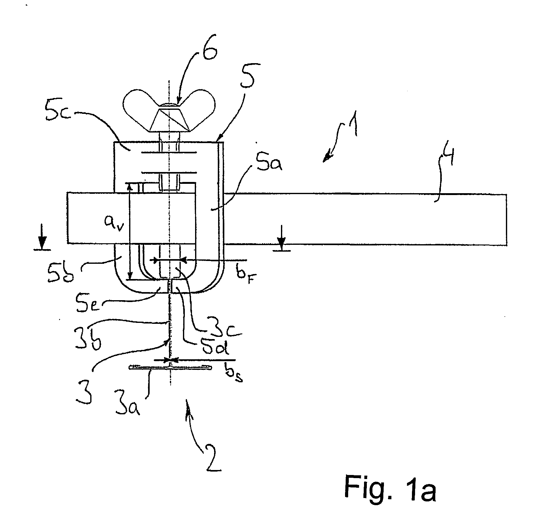
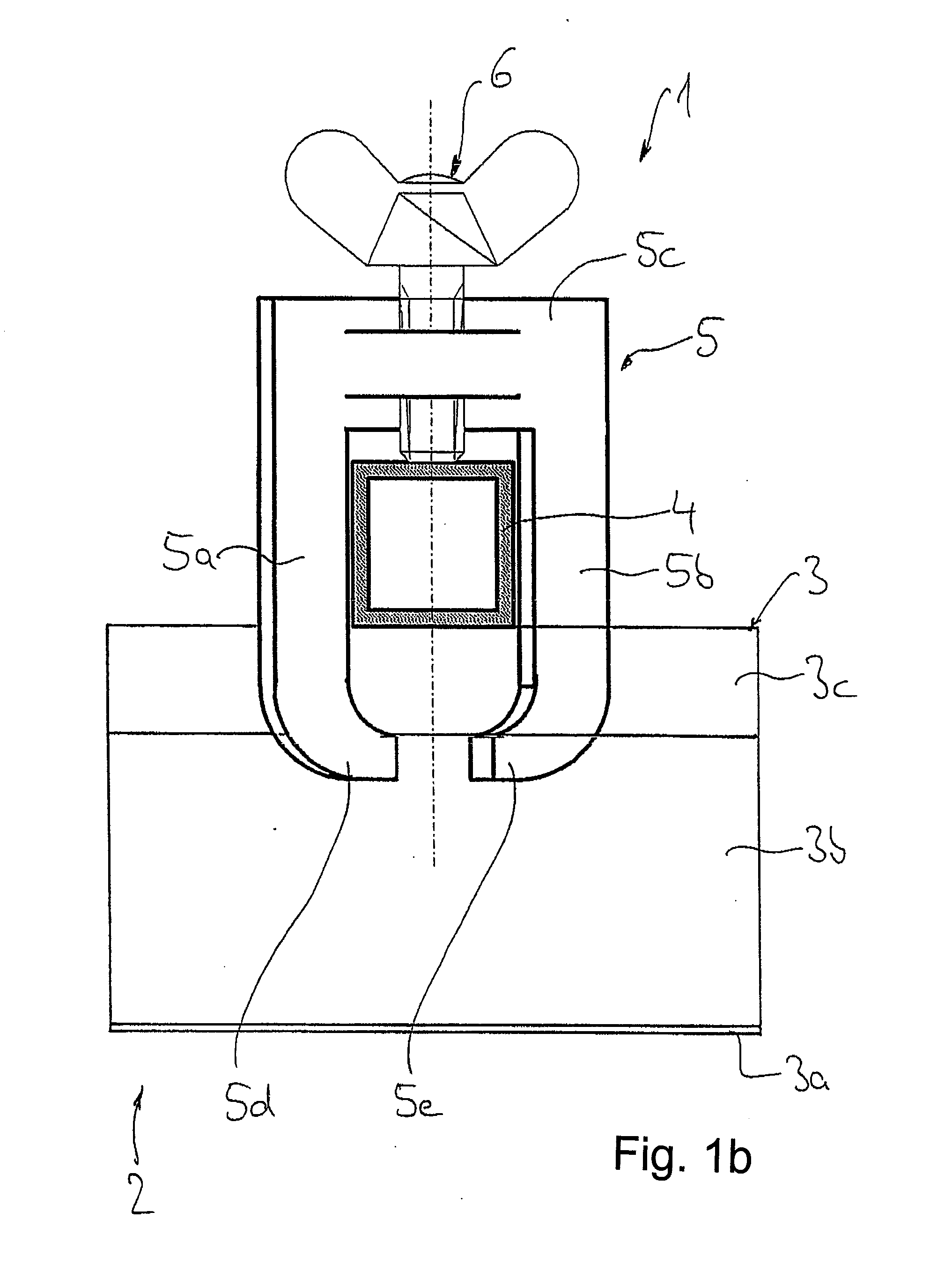
[0028]FIG. 1 shows a mount 1 for a ceiling system 2. The ceiling system comprises a plurality of girders 3, which form a latticed structure made of multiple girders situated perpendicularly to one another. In general, the girders have an inverted T-profile, in which individual cassette-shaped ceiling elements (not shown) are fixed in a known manner on the lower T-base 3a in FIG. 1. A vertical T-web 3b of the T-girder 3 extends upward starting from the horizontal T-base 3a and ends there in an enlarged flange 3c, which has an increased width in relation to the T-web 3b and thus receives the clamping force of the mounting clamp 1 as described in greater detail hereinafter.

[0029] The mount 1 essentially comprises a bridge member 4 in the form of a rectangular tube, which extends between two T-girders 3 and is fixed thereon. In a section not shown in FIG. 1, the bridge 4 carries a nozzle clamp which fixes a sprinkler nozzle (also not shown) precisely in position in such a way that the ...


PUM


Abstract

A mount for situating a sprinkler nozzle of a fire extinguishing system in an opening of a suspended ceiling system, the fire extinguishing system having a main line to which a downwardly directed sprinkler nozzle is connected by a flexible hose line, a bridge provided on the top side of the ceiling system extending essentially parallel thereto, the bridge being connected to girders of the ceiling system by a detachable clamp, and the sprinkler nozzle being at least indirectly attached to the bridge.

Description

CROSS REFERENCE TO RELATED APPLICATIONS [0001] This application claims priority from U.S. provisional patent application No. 60 / 818,994, filed Jul. 7, 2006. Priority is also claimed based on Federal Republic of Germany patent application no. DE 20 2006 009 429.6, filed Jun. 16, 2006.BACKGROUND OF THE INVENTION [0002] The present invention relates to a mount for situating a sprinkler nozzle of a fire extinguishing system in an opening of a suspended ceiling system. [0003] A wide variety of mounts for sprinkler nozzles are known in the art. For example, published German patent application no. DE 197 09 916 discloses a bridge comprised of a folded sheet-metal blank and fastened via connection elements, which also comprise a sheet-metal blank, to two girders, by inserting the connection elements into slots of the girder. The connection elements are screwed together with the sheet-metal blank in this state and they thus fix the bridge having the sprinkler nozzle attached thereto to two g...

Claims


Application Information

Patent Timeline
Patent Type & Authority Applications(United States)
IPC IPC(8): A62C37/50
CPCA62C35/68
Inventor PAULIG, GERD
Owner WITZENMANN GMBH
Learn More