Display Unit Installing Structure for Refrigerator

Inactive Publication Date: 2007-12-20
LG ELECTRONICS INC
View PDF30 Cites 16 Cited by
  • Summary
  • Abstract
  • Description
  • Claims
  • Application Information

AI Technical Summary

Benefits of technology

[0049] According to the present invention so configured, the display unit can be retractably mounted to the front surface of the refrigerator door. Therefore, there are some advantages in that a better field of vision can be substantially obtained enough for a user to view the display unit regardless of pos

Problems solved by technology

However, the conventional display unit installing structure for a refrigerator so configured has the following problems.
Nevertheless, since the display unit is fixed to the front surface of the refrigerating chamber door 2b, there is a disadvantage in that an inferior filed of vision may be obtained depending on positions of the user.
Therefore, since there is no possibility of the change in design of the external appearance of the refrigerator, the external appearance of the front surface of the refrigerator becomes monotonous.
In addition, if the display unit 6 is fixed to the front surface of the refrigerating chamber door 2b, heat generated while the display unit 6 is operated m

Method used


Image

  • Display Unit Installing Structure for Refrigerator
  • Display Unit Installing Structure for Refrigerator
  • Display Unit Installing Structure for Refrigerator

Examples


first embodiment

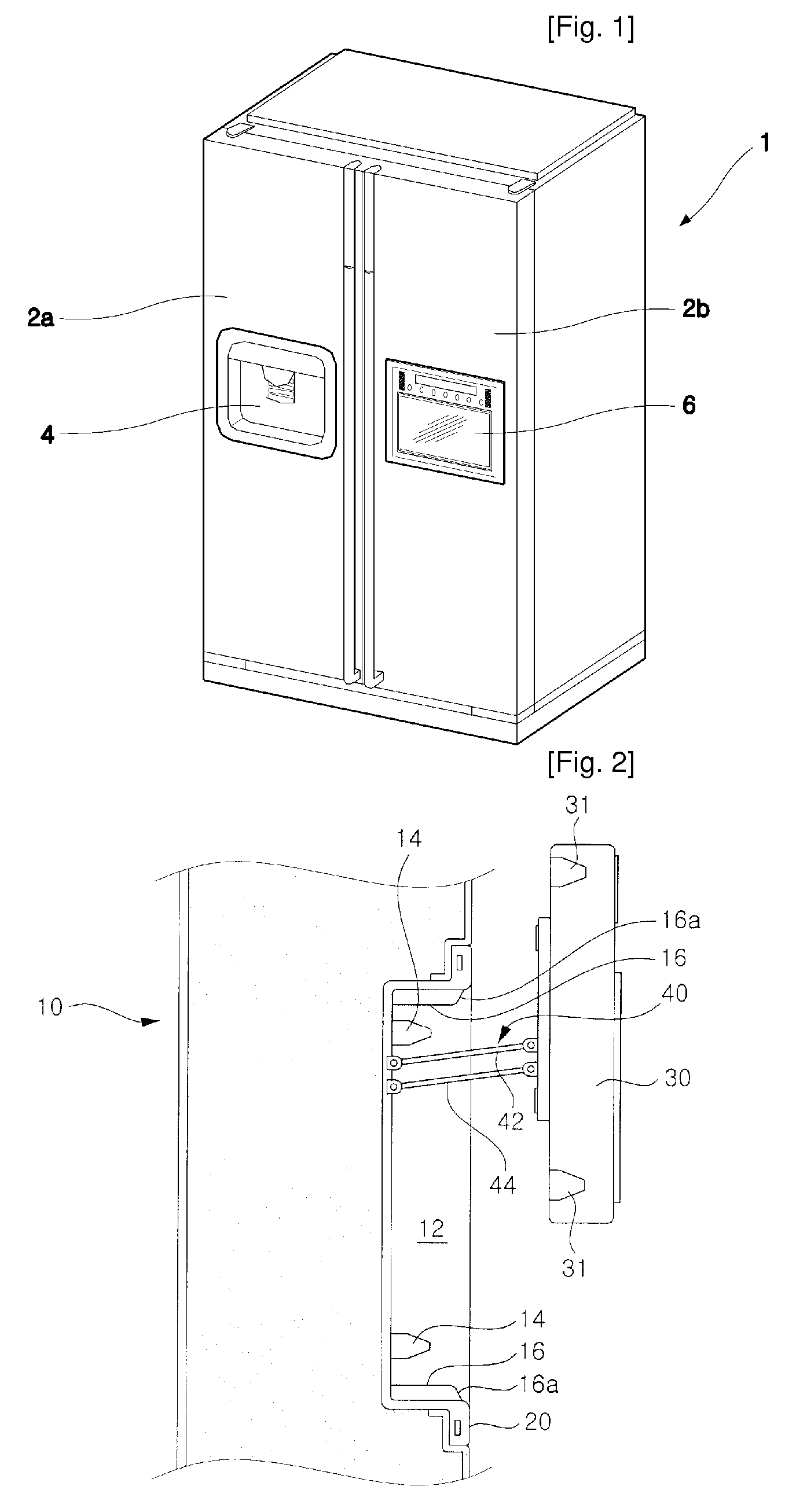
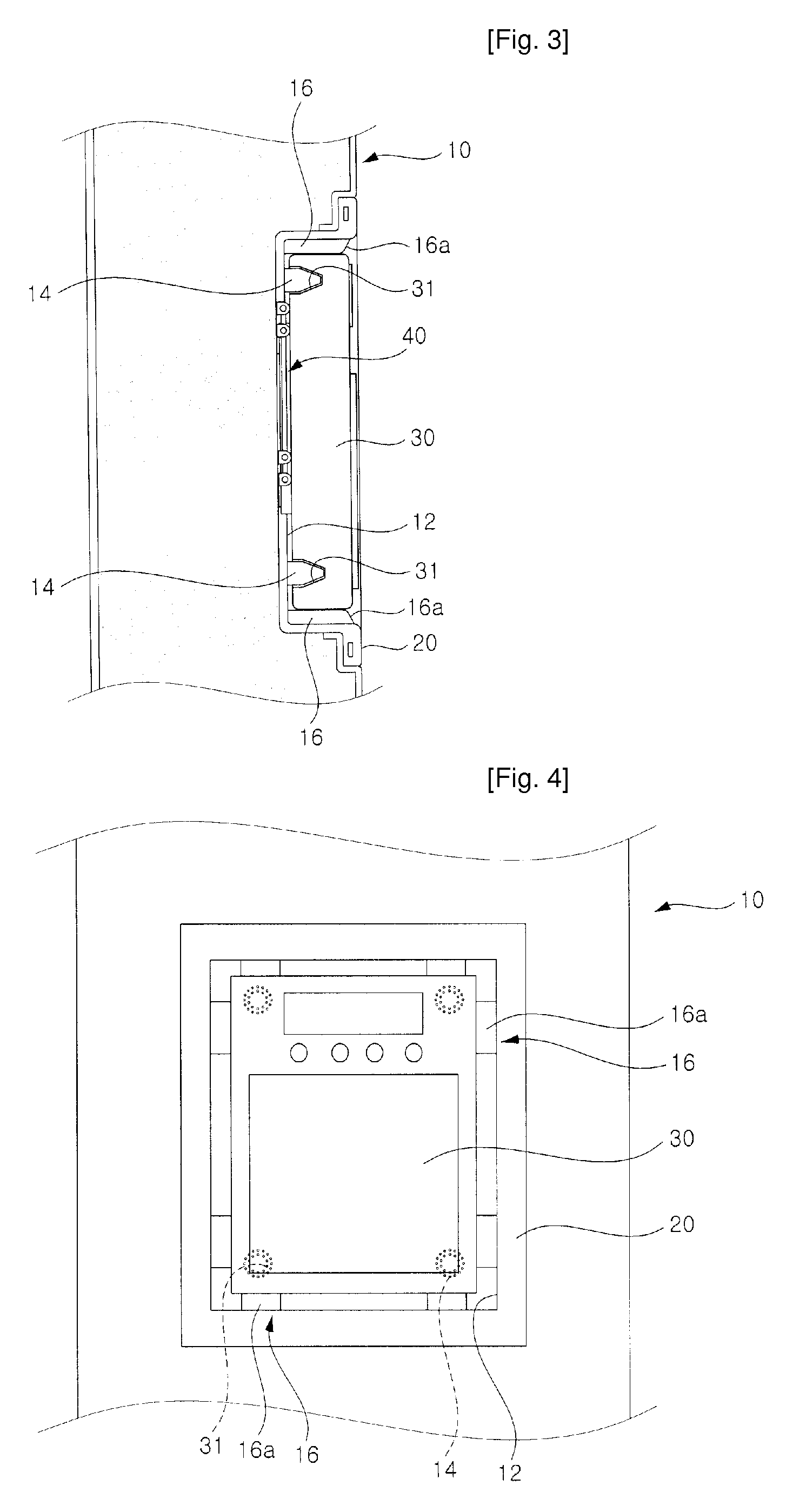
[0071]FIG. 2 shows a state where a display unit is withdrawn by using a display unit installing structure for a refrigerator according to the present invention, and FIGS. 3 and 4 show a state where the display unit is accommodated according to the embodiment shown in FIG. 2.

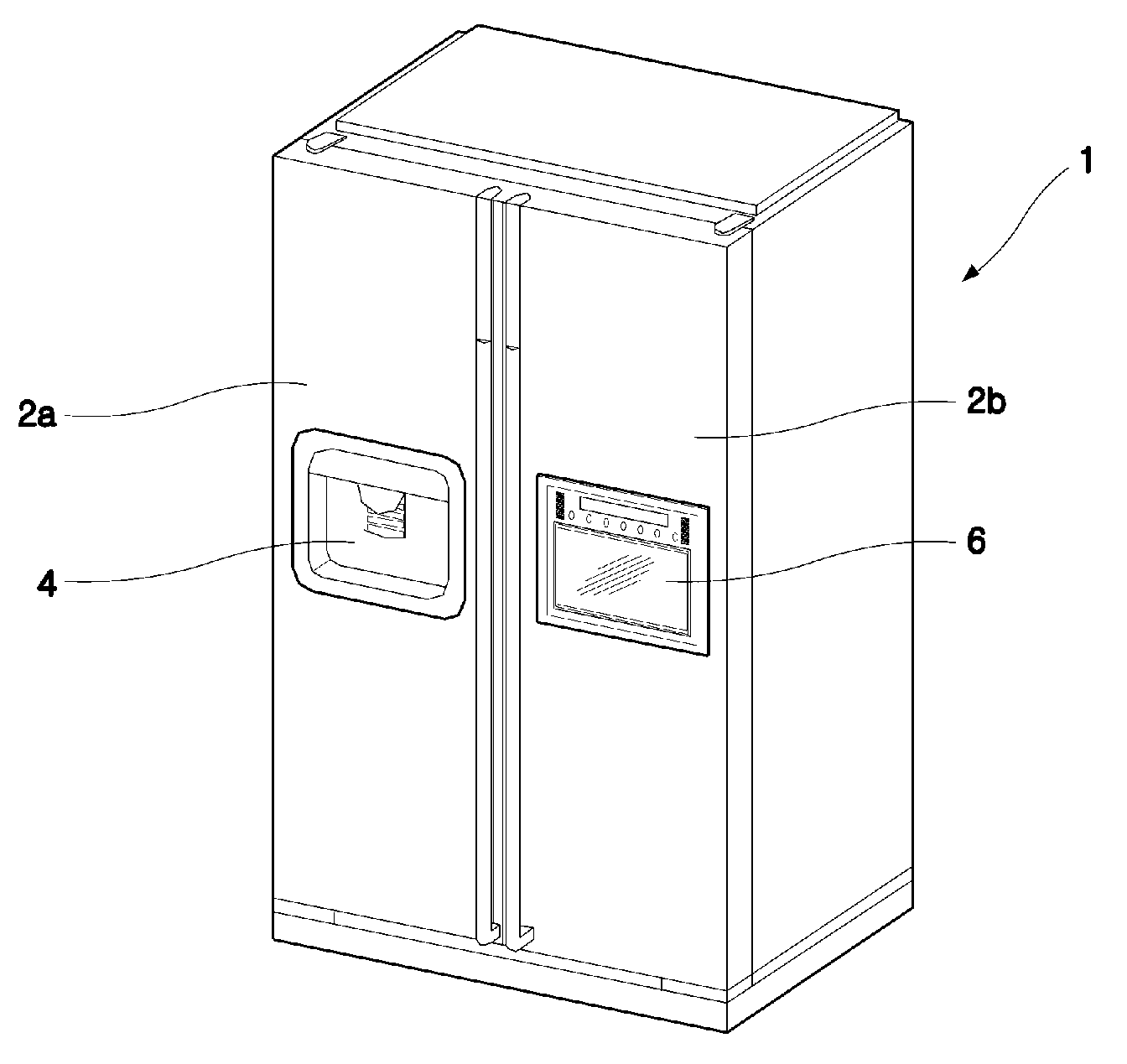
[0072] As shown in these figures, an accommodating unit 12 is provided in a front surface of a refrigerator door 10. The accommodating unit 12 is formed into a flat box with an open front face. In this embodiment, the accommodating unit 12 is defined by a recess member 20 installed on a front surface of the door 10. That is, the recess member 20 is installed on the front surface of the door 10, and thus, the accommodating unit 12 can be defined by a concave portion of the recess member 20. Alternatively, the accommodating unit 12 can be formed integrally with the front surface of the door 10.

[0073] A display unit 30 is retractably installed in the accommodating unit 12. Thus, it is preferred that the accommodati...

second embodiment

[0089] Next, a display unit installing structure for a refrigerator according to the present invention will be described with reference to the accompanying drawings.

[0090]FIG. 5 shows a state where a display unit is withdrawn by using the display unit installing structure for a refrigerator according to the second embodiment of the present invention, FIG. 6 shows a recess member and a bracket constituting the second embodiment shown in FIG. 5, and FIG. 7 shows a process of accommodating and / or withdrawing the display unit according to the second embodiment shown in FIG. 5.

[0091] As shown in the figures, a display unit 30 is retractably installed in an accommodating unit 12 provided on a front surface of a refrigerator door 10. The accommodating unit 12 is defined by a recess member 20 provided on the front surface of the door 10. Further, a link mechanism 40 is provided to guide the accommodation and withdrawal of the display unit 30.

[0092] In this embodiment, the link mechanism 4...

third embodiment

[0108] Hereinafter, a display unit installing structure for a refrigerator according to the present invention will be explained.

[0109]FIG. 8 shows the third embodiment of the display unit installing structure according to the present invention.

[0110] As shown in the figure, a link member 42 of the link mechanism 40 is a two-point linkage. Thus, the link mechanism 40 can guide the accommodation / withdrawal of the display unit 30 and simultaneously adjust the tilting angle of the display unit 30.

[0111] Further, the display unit 30 is provided with a handle 31. In the illustrated embodiment, the handle 31 is formed concave by inwardly depressing a portion of a bottom surface of the display unit 30. So long as the handle 31 can be used to allow a user to pull the display unit 30 received in the accommodating unit 12 with his / her hand, it can formed in any shape.

[0112] Further, the other configuration for accommodating and / or withdrawing the display unit 30, including the accommodating...


PUM


Abstract

The present invention relates to a display unit installing structure for a refrigerator. The present invention comprises an accommodating unit which is formed by depressing a portion on a front surface of a door and in which a display unit for displaying a variety of information thereon and inputting operating signals are retractably installed; a link mechanism for guiding accommodation and withdrawal of the display unit and tiltably supporting the display unit withdrawn from the accommodating unit at a predetermined angle; and a locking means for preventing the display unit from being inadvertently escaping from the accommodating unit. According to the present invention, there is an advantage in that the display unit can be retractably installed on the front surface of the refrigerator door.

Description

TECHNICAL FIELD [0001] The present invention relates to a refrigerator, and more particularly, to a display unit installing structure for a refrigerator which can be used to retractably mount a display unit to a portion on a refrigerator door. BACKGROUND ART [0002] Refrigerators are household appliances for storing foods in a refrigerating or freezing chamber thereof in a refrigerated or frozen state. In addition to a traditional function of storing foods therein, recently available refrigerators are provided with additional devices such as a dispenser and home bar to allow a user to withdraw water or foods stored in the refrigerator without opening the door, so that their convenience of user can be increased. Further, refrigerators may be provided with a display unit on which a variety of information can be displayed and operating signals can be inputted. [0003]FIG. 1 shows a refrigerator mounted with a display unit according to a prior art. [0004] As shown in the figure, a main bo...

Claims


Application Information

Patent Timeline
IPC IPC(8): F25D23/02
CPCF16M11/04F16M11/12F16M11/2092F16M13/02F25D2400/361F16M2200/063F25D29/005F25D2400/18F16M2200/041
Inventor OH, SEUNG-JINLEE, SOO-BEOMWOO, KI-CHEOLLEE, IK-KYUKIM, JIN-HYUN
Owner LG ELECTRONICS INC
Why Eureka
Try Eureka