Driver arrangement for LED lamps

a technology of led lamps and drivers, applied in the direction of electric variable regulation, process and machine control, instruments, etc., can solve the problems of inability to provide a consistent safety insulating barrier, prior art solutions do not lend themselves to dimming functions,

Active Publication Date: 2007-12-20
ABL IP HLDG
View PDF6 Cites 105 Cited by
  • Summary
  • Abstract
  • Description
  • Claims
  • Application Information

AI Technical Summary

Benefits of technology

[0004] The need is therefore felt for high-efficiency and low-cost / low-size driver arrangements for LED lamps such as e.g. self-ballasted high-flux, dimmable LED lamps.

Problems solved by technology

Conventional driver arrangements for LED lamps typically implement self-oscillating fly-back topologies with bipolar transistor and basic transformer structure, which are unable to provide any consistent safety insulating barrier.
Additionally, these prior art solutions do not lend themselves to implement a dimming function.

Method used


Image

  • Driver arrangement for LED lamps
  • Driver arrangement for LED lamps
  • Driver arrangement for LED lamps

Examples


Embodiment Construction

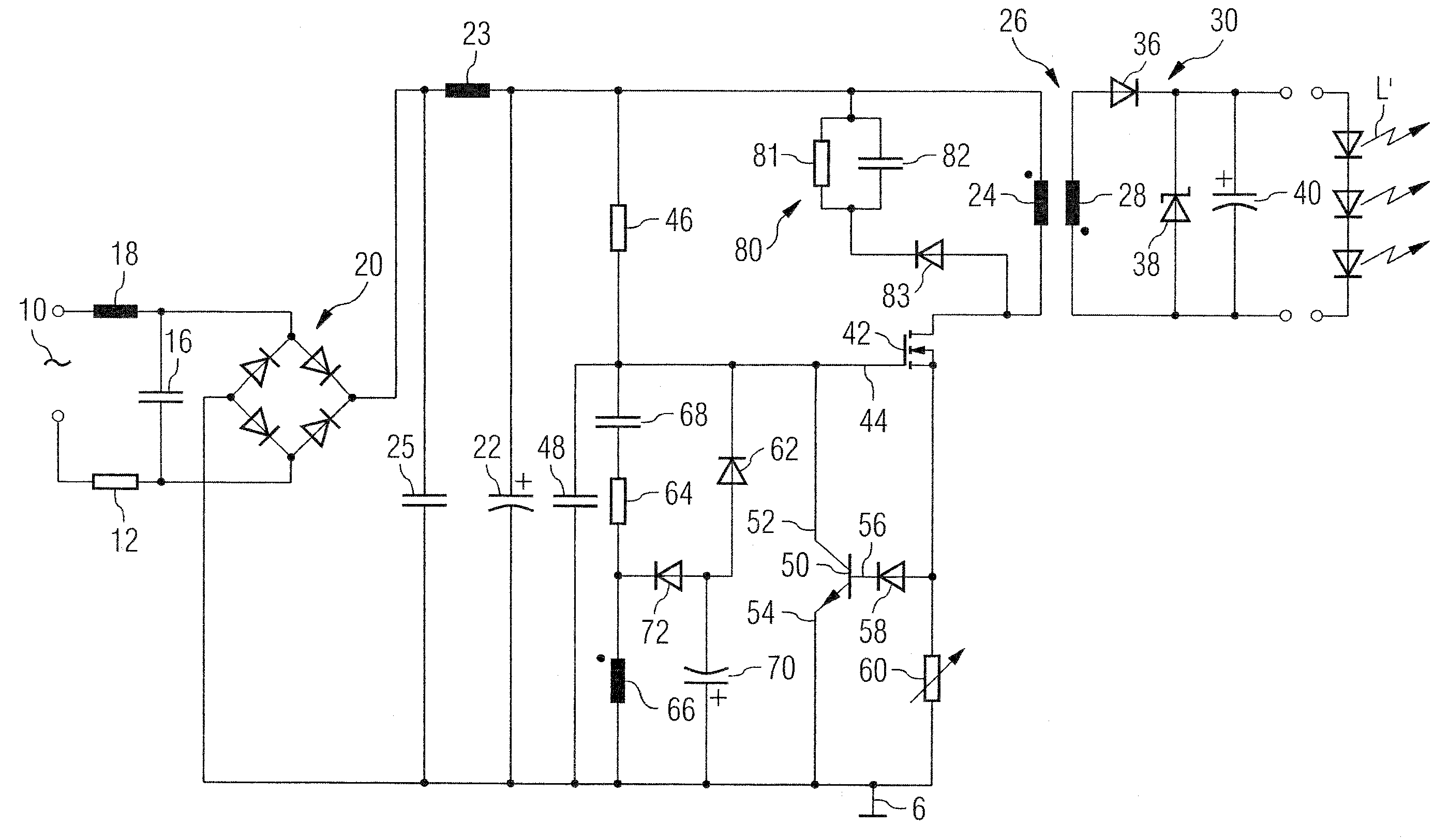
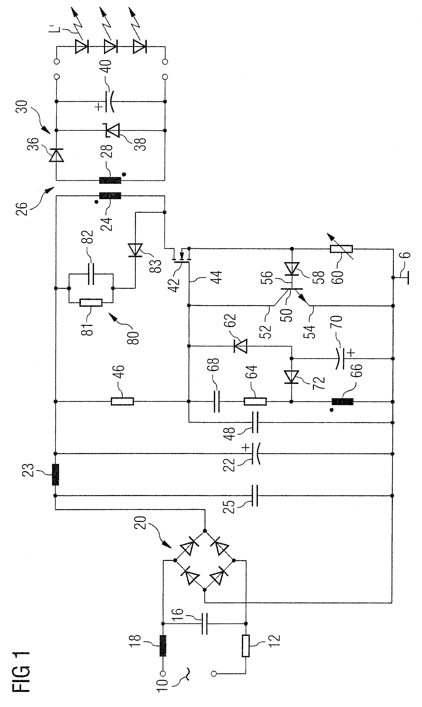
[0017] The circuit diagram of FIG. 1 is representative of a driver circuit for use in feeding one or more LED lighting sources L from a mains input voltage applied between two input terminals 10.

[0018] The mains input voltage applied across the terminal 10 goes first through an Electro-Magnetic Interference (EMI) filter. This is typically comprised e.g. of a resistor 12 having cascaded thereto a low-pass LC filter comprised of a capacitor 16 and an inductor 18. The filtered input voltage is then fed to a bridge rectifier 20 to produce a rectified voltage which, after filtering via a LC network comprised of an inductor 23 and a capacitor 25, is made available across a capacitor 22, preferably comprised of an electrolytic capacitor.

[0019] The voltage across the capacitor 22 forms a so-called “DC bus voltage” (referred to ground G) which is subject to controlled switching as better detailed in the following in order to feed the primary winding 24 of a voltage step-down transformer 26...


PUM


Abstract

A driver arrangement for LED light sources includes a transformer having primary and secondary winding connections. A first electronic switch (SW1) controls current flow through the primary winding, and a sensing resistor is coupled to the primary winding to produce a current sensing signal. A second electronic switch (SW2) is sensitive to the sensing signal to switch off SW1 as current flow through the primary winding reaches a given threshold. SW1 is thus alternatively turned-on and off in alternating turn-on and switch-off phases to power the LED light source via the secondary winding. SW1 is a field effect transistor, preferably a MOSFET. The transformer is SELV-rated. The sensing resistor may be a variable resistor to adjust the duration of the on/off phases to permit controlled dimming.

Description

FIELD OF THE INVENTION [0001] The invention relates to LED lamps and, more specifically, to driver arrangements for LED lamps. DESCRIPTION OF THE RELATED ART [0002] Light emitting diodes (or LEDs) are meeting with an increasing success in their use as lighting sources, that is as lamps. This applies particularly to so-called high-flux (HF) LED lamps. [0003] Conventional driver arrangements for LED lamps typically implement self-oscillating fly-back topologies with bipolar transistor and basic transformer structure, which are unable to provide any consistent safety insulating barrier. As a consequence, no “hot” parts of the circuitry can be left exposed and all the components in the driver arrangement must be enclosed within an insulating housing (comprised e.g. of plastics such as polycarbonate). In practice, such arrangements can be applied only to simple battery chargers and low-power (1-2 W) LED lamps. Additionally, these prior art solutions do not lend themselves to implement a ...

Claims


Application Information

Patent Timeline
Patent Type & Authority Applications(United States)
IPC IPC(8): H05B41/16H05B44/00
CPCH02M3/3385Y02B20/347H05B33/0815Y02B20/30H05B45/375
Inventor HE, XI YUANMA, RUISCILLA, GIOVANNI
Owner ABL IP HLDG
Why Eureka
Try Eureka