
Camera with interchangeable lenses having electrical circuitry

a technology of electrical circuitry and interchangeable lenses, which is applied in the field of digital cameras with interchangeable lenses, can solve the problems of increasing power consumption of digital cameras, combustible foreign bodies such as dust, and affecting the effect of electrical leakage, so as to prevent the spread of fir

Inactive Publication Date: 2007-12-20
PANASONIC CORP
View PDF13 Cites 10 Cited by
  • Summary
  • Abstract
  • Description
  • Claims
  • Application Information

AI Technical Summary

Benefits of technology

[0013] An object of the present invention is to provide an interchangeable lens type camera which is so safe as to prevent spread of fire when dust strays into the interior of the camera to cause heating and / or electrical leakage of the electric circuitry and invite ignition.
[0027] According to the present invention, component parts, circuits, and wiring which transmit or consume a large electric power are enclosed by flame-retardant members, thus providing an effect of preventing spread of fire in the event of an ignition which is caused by the interior of the housing being abnormally heated or by electrical leakage.

Problems solved by technology

Since cameras consume a large electric power, safety measures are needed against heat generation and other phenomena caused by their electric circuitry.
Since the internal electric circuitry is exposed to the exterior via the lens mount section, combustible foreign bodies, such as dust, are likely to enter.
The power consumption of digital cameras is increasing, and an electric current as large as several A (ampere) may flow in the wiring of the printed circuit board.
Electrical leakage may also occur.
Under such situations, ignition inside the camera or camera malfunctioning may occur due to heating and / or electrical leakage, thus allowing the user to be injured.

Method used


Image

  • Camera with interchangeable lenses having electrical circuitry
  • Camera with interchangeable lenses having electrical circuitry
  • Camera with interchangeable lenses having electrical circuitry

Examples


embodiment 1

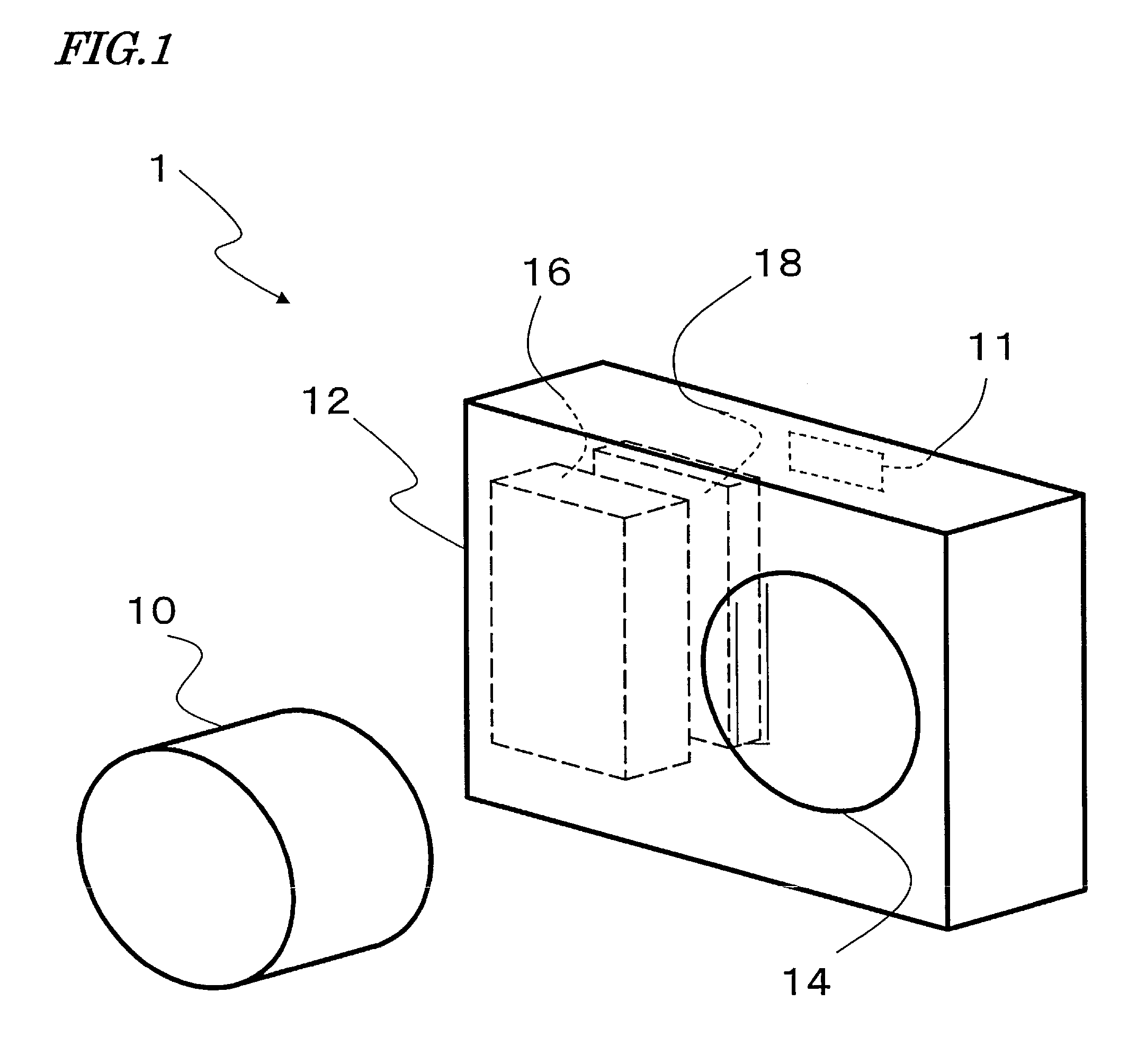
[0051]FIG. 1 schematically shows the exterior appearance of an interchangeable lens type camera 1 according to the present embodiment, which allows a lens 10 to be attached to or detached from it.

[0052] The interchangeable lens type camera 1 hereinafter referred to as the “camera 1”) mainly includes a lens 10 and a camera housing (camera case) 12. The lens 10 is fixed to a mount section 14 which is provided in the camera housing 12.

[0053] When the lens 10 is detached from the mount section 14, the interior of the camera housing 12 is exposed to the exterior. External light (subject image) travels through the lens 10 to enter the camera housing 12, and enters an imaging device (not shown). Thus, the subject can be imaged by using the camera 1.

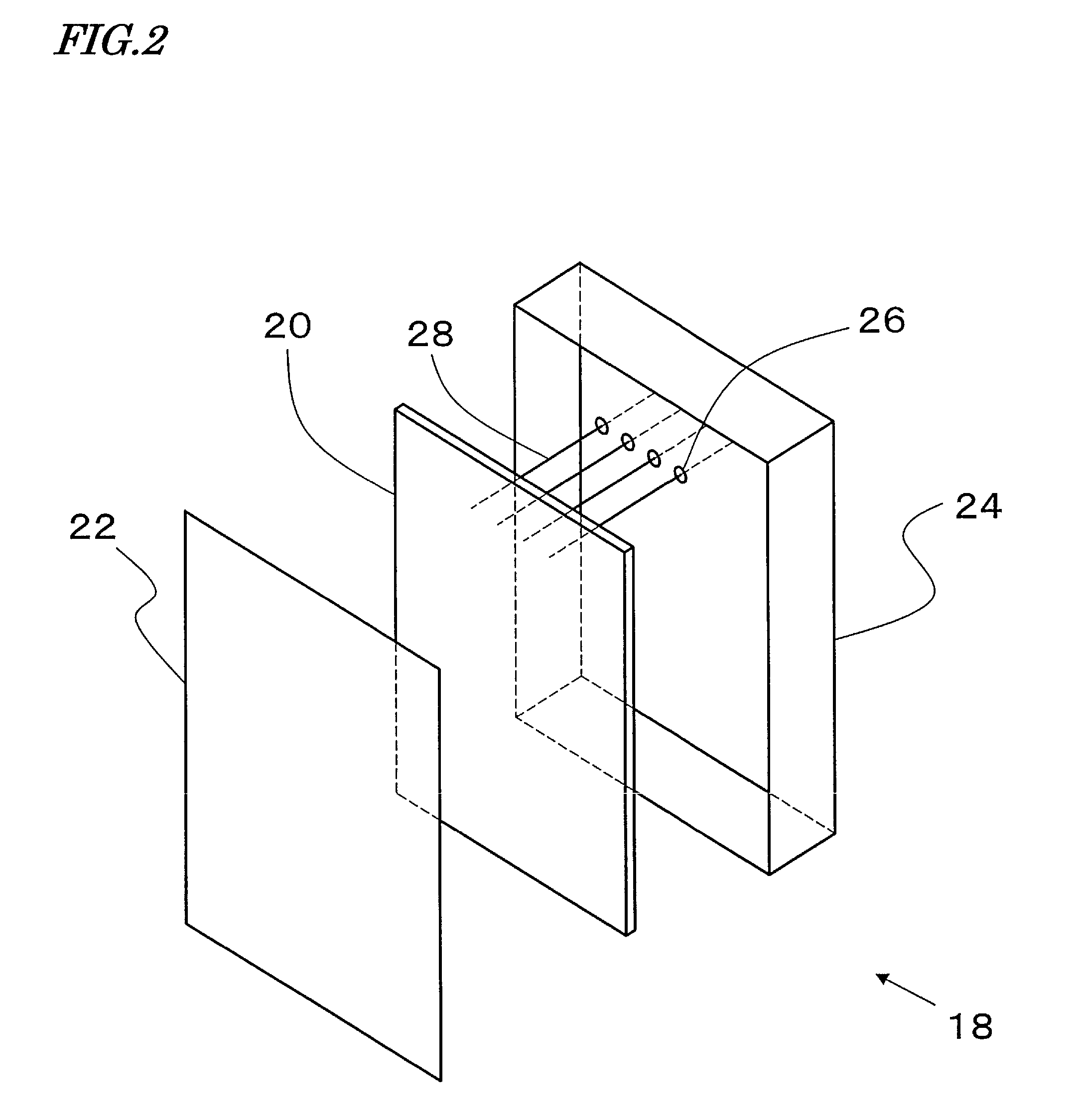
[0054] At the left-hand side of the interior of the camera housing 12, as the camera 1 is viewed from the side of the lens 10, a subenclosure 18 (specifically described later) and a battery box 16 in which a battery pack for the camera 1 is t...

embodiment 2

[0101]FIG. 9 schematically shows the exterior appearance of an interchangeable lens type camera 2 (hereinafter referred to as the “camera 2”) according to the present embodiment.

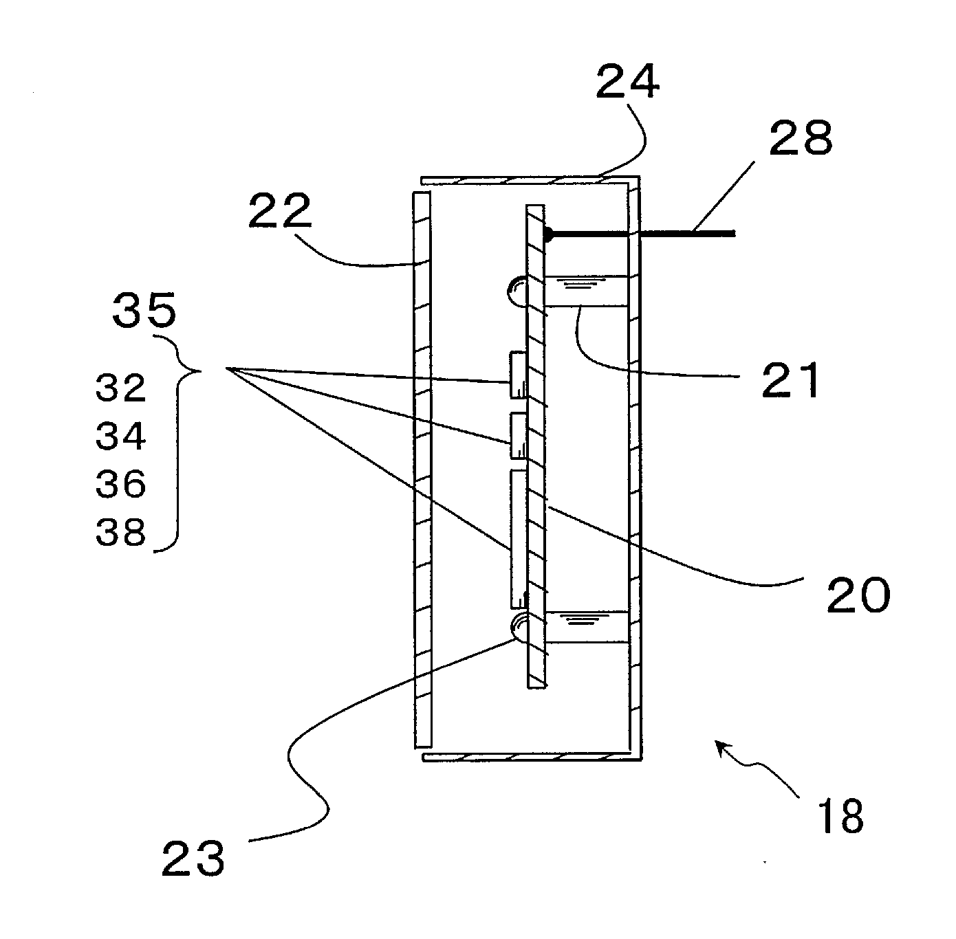
[0102] The present embodiment illustrates a case where the subenclosure 18 is constructed as portions of other component parts. In the housing 12, an aluminum frame 60 for improving the strength is built. The aluminum frame 60 doubles as part of the battery box 16, and also doubles as part of the subenclosure 18. Moreover, some of the faces of the battery box 16 are extended to compose a part of the subenclosure 18. In other words, the subenclosure 18 according to the present embodiment includes portions of the aluminum frame 60 and the battery box 16.

[0103]FIG. 10 shows relative positioning between the aluminum frame 60, the battery box 16, and the printed circuit board 20. The aluminum frame 60 is opened in the form of a window where an imaging unit is to be installed. One end thereof is extended in the ...

embodiment 3

[0117]FIG. 13 shows a construction in which a memory holder 70 is disposed between the printed circuit board 20 and the aluminum frame 60. The memory holder 70 has a slot 72 for memory insertion, and a corresponding aperture 59 for the memory insertion is formed in the side skirt 56 of the battery box. Although not shown, a corresponding aperture is also provided in a side face of the housing.

[0118] Most digital cameras have a function of recording image data to not only an internal memory but also an external memory. In doing this, the memory holder 70 serves as an interface with the external memory. There is no particular limitation as to the external memory, e.g., a semiconductor memory, an optical disk, a magnetic disk.

[0119] A relatively large electric power is likely to be used for performing a write, a read, or driving for an external memory, and thus it is preferably disposed near a printed circuit board 20 which is the power supplying source. In other words, it may prefer...


PUM


Abstract

There is provided an interchangeable lens type camera which is so safe as to prevent spread of fire when dust strays into the interior of the camera to cause heating and / or electrical leakage of the electric circuitry and invite ignition. The camera includes a case having a mount section for mounting a detachable lens; electric circuitry provided within the case; and a member covering at least a portion of the electric circuitry to prevent the electric circuitry from being exposed to the exterior when the lens is detached from the mount section.

Description

BACKGROUND OF THE INVENTION [0001] 1. Field of the Invention [0002] The present invention relates to a camera having electric / electronic circuitry. More particularly, the present invention relates to a digital camera with an interchangeable lens, in which countermeasures against heating and / or electrical leakage are taken for internal electric / electronic circuitry. [0003] 2. Description of the Related Art [0004] Cameras have conventionally been widely prevalent as products which image subjects by operating mechanical structures such as shutters. Traditional cameras were only equipped with mechanical structures, and it is in the recent years that electric / electronic circuitry (hereinafter collectively referred to as “electric circuitry”) has come to be internalized for effecting various control. [0005] In particular, the recording medium for subjects has conventionally been a film, but semiconductor memory has begun to be used in the recent years. Such cameras are widely known as dig...

Claims


Application Information

Patent Timeline
Patent Type & Authority Applications(United States)
IPC IPC(8): H04N5/225
CPCH04N5/2251H04N5/23241H04N5/2254H04N23/52H04N23/55H04N23/65
Inventor MORISHITA, SEIKINAKADA, MASAHIROMORI, TETSUYAHAYASHI, JUNKO
Owner PANASONIC CORP
Learn More