Air conditioning apparatus

a technology for air conditioning apparatus and air conditioner, which is applied in the direction of domestic cooling apparatus, heating types, instruments, etc., can solve the problem that the air conditioning apparatus does not have the function of proactively extinguishing fir

Inactive Publication Date: 2009-01-08
DAIKIN IND LTD
View PDF3 Cites 8 Cited by
  • Summary
  • Abstract
  • Description
  • Claims
  • Application Information

AI Technical Summary

Benefits of technology

[0044]According to this air conditioning apparatus, since the carbon dioxide can be emitted to the electric component assembly from the high-pressure portion of the refrigerant circuit through which high-pressure refrigerant flows during the refrigeration cycle operation, and from a low-pressure portion of the refrigerant circuit through which low-pressure refrigerant flows during the refrigeration cycle operation, a larger amount of the carbon dioxide can be emitted in a short amount of time in comparison with cases in which the carbon dioxide is emitted from either one of the high-pressure portion or low-pressure portion.

Problems solved by technology

An air conditioning apparatus such as is described above has the effect of preventing to the extent possible the spread of fire to the other components of the indoor units when the electric component assembly ignites due to an abnormal temperature increase, but such an air conditioning apparatus does not have the function of proactively extinguishing the fire.

Method used


Image

  • Air conditioning apparatus
  • Air conditioning apparatus
  • Air conditioning apparatus

Examples


embodiment 1

[0069](1) Configuration of Air Conditioning Apparatus

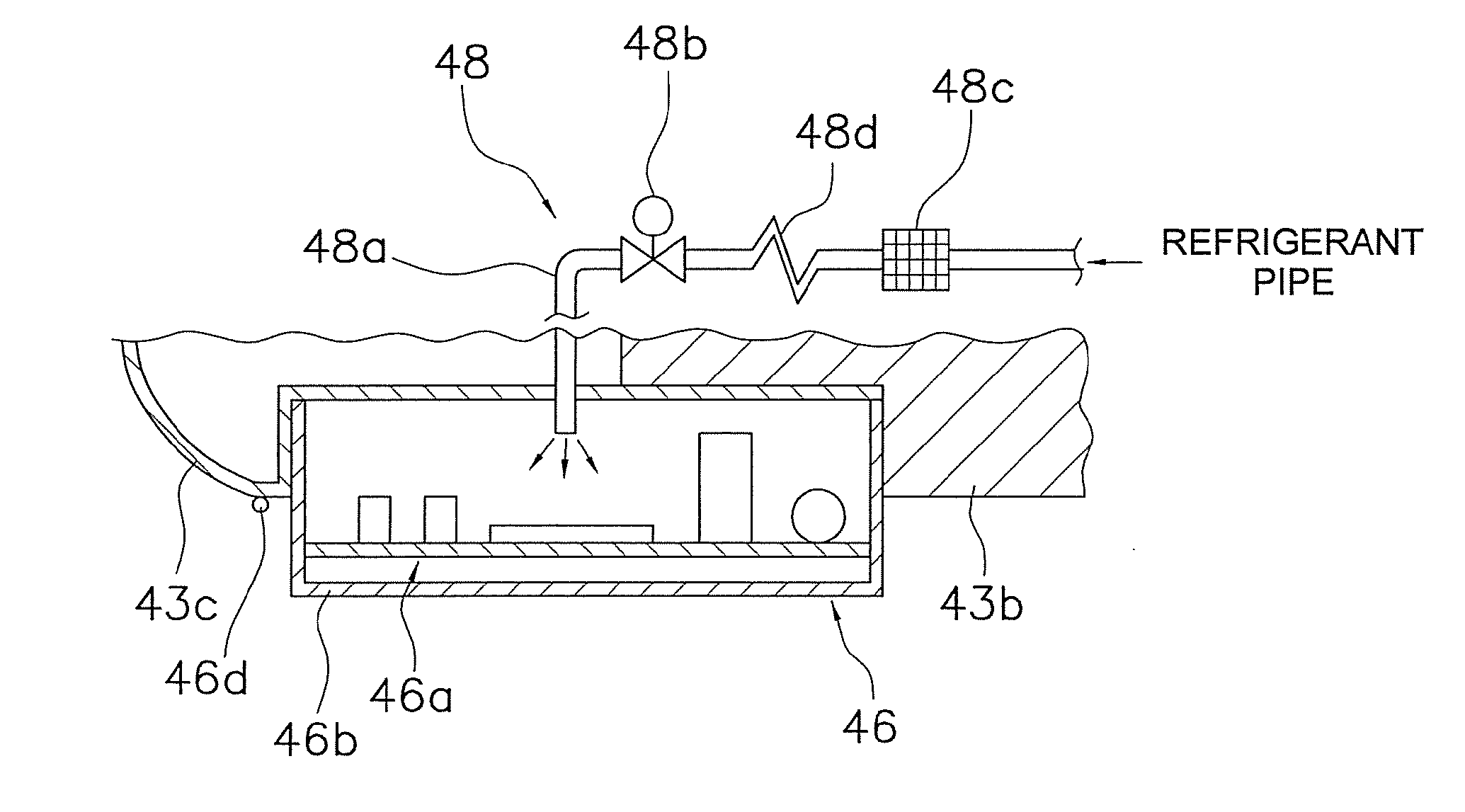
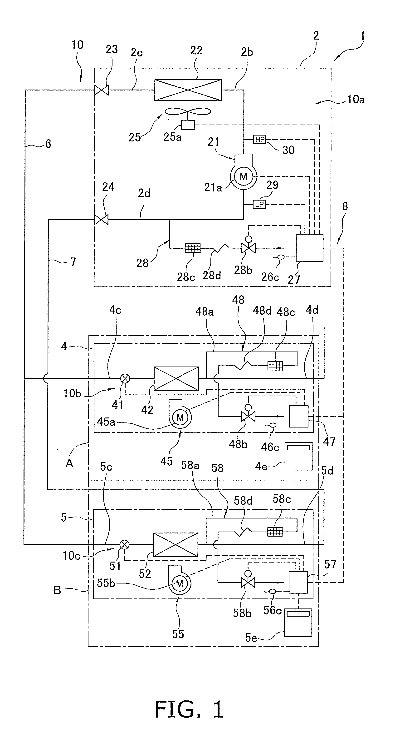
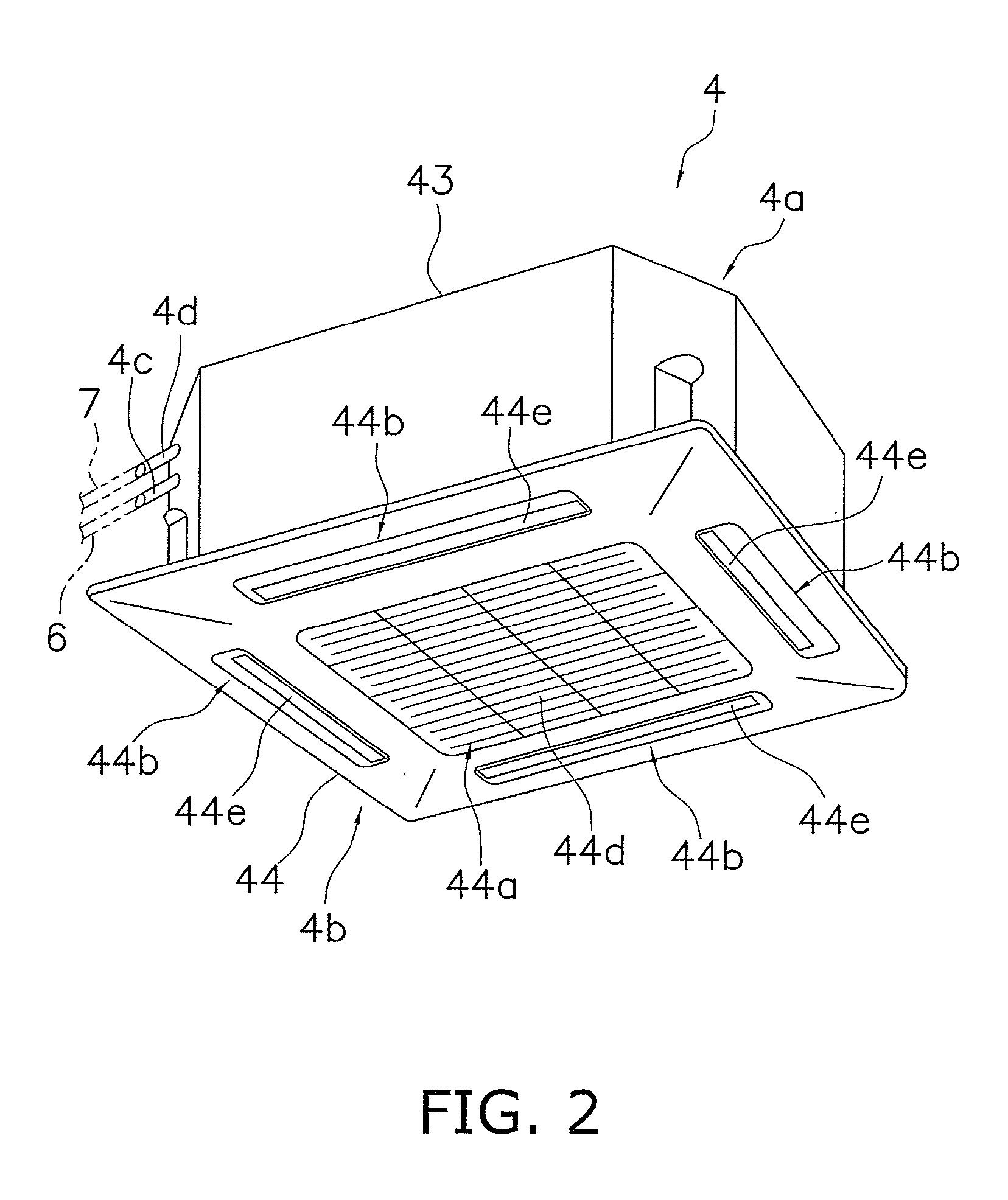
[0070]FIG. 1 is a schematic structural view of an air conditioning apparatus 1 according to embodiment 1 of the present invention. The air conditioning apparatus 1 is an apparatus used to cool the interior of a building or the like by performing a vapor compression-type refrigeration cycle operation. The air conditioning apparatus 1 mainly includes an outdoor unit 2, a plurality (two in this case) of indoor units 4, 5, and refrigerant communication pipes 6, 7 for connecting the outdoor unit 2 with the indoor units 4, 5. Specifically, a vapor compression refrigerant circuit 10 of the air conditioning apparatus 1 of the present embodiment is configured by connecting the outdoor unit 2, the indoor units 4, 5, and the refrigerant communication pipes 6, 7. Carbon dioxide (CO2) is filled as a refrigerant with refrigerator oil in the refrigerant circuit 10 of the air conditioning apparatus 1, and for example, a refrigerant cycle operatio...

second embodiment

[0167](1) Configuration of Air Conditioning Apparatus

[0168]FIG. 21 is a schematic structural drawing of an air conditioning apparatus 101 according to the second embodiment of the present invention. Similar to the air conditioning apparatus 1 according to embodiment 1, the air conditioning apparatus 101 is an apparatus used to cool the interiors of buildings and the like by performing a vapor compression refrigeration cycle operation, and mainly comprises an outdoor unit 102, a plurality (two in this case) of indoor units 4, 5, and refrigerant communication pipes 6, 7 for connecting the outdoor unit 102 with the indoor units 4, 5, constituting a refrigerant circuit 110 that uses carbon dioxide as a refrigerant. Similar to the air conditioning apparatus 1 according to embodiment 1, the air conditioning apparatus 101 according to the present embodiment is provided with refrigerant emission pipes 28, 48, 58 as refrigerant emission means that can emit the carbon dioxide from the refrige...


PUM


Abstract

To provide an air conditioning apparatus having a function for extinguishing fire when an electric component assembly ignites. An air conditioning apparatus (1) comprises a vapor compression refrigerant circuit (10) that uses carbon dioxide as a refrigerant, an electric component assembly (26, 46, 56) for controlling an operation for structural devices, and a refrigerant emission pipe (28, 48, 58) capable of emitting carbon dioxide from the refrigerant circuit (10) to the electric component assembly (26, 46, 56).

Description

TECHNICAL FIELD[0001]The present invention relates to an air conditioning apparatus, and particularly to an air conditioning apparatus comprising electric component assembly for controlling the operations of structural devices.BACKGROUND ART[0002]Within the field of air conditioning apparatuses comprising electric component assembly, a technique has been disclosed in which the frames of the electric component assembly and its attached components are configured from a flame-retardant material (see Patent Documents 1 and 2).[0003]<Patent Document 1>[0004]Japanese Laid-open Patent Application No. 7-293927[0005]<Patent Document 2>[0006]Japanese Laid-open Patent Application No. 10-78242DISCLOSURE OF THE INVENTION[0007]An air conditioning apparatus such as is described above has the effect of preventing to the extent possible the spread of fire to the other components of the indoor units when the electric component assembly ignites due to an abnormal temperature increase, but ...

Claims


Application Information

Patent Timeline
Patent Type & Authority Applications(United States)
IPC IPC(8): F25D29/00F24F1/0047F24F1/0059F24F1/0068
CPCF24F1/0003F24F1/0007F24F1/06F24F1/50F24F11/0086F24F2011/0095F24F2013/0616F25B9/008F25B49/005F25B2309/06F25B2700/1931F25B2700/1933F24F2013/207F24F11/30F24F11/33F24F1/0047F24F1/0059F24F1/0068F25B49/02F25B1/00F25B45/00
Inventor YABU, TOMOHIRO
Owner DAIKIN IND LTD
Why Eureka
Try Eureka