Eureka AIR delivers breakthrough ideas for toughest innovation challenges, trusted by R&D personnel around the world.

Communication Apparatus, Method For Controlling Communication Apparatus, Control Program, And Recording Medium

Inactive Publication Date: 2007-12-20
SHARP KK
View PDF6 Cites 4 Cited by
  • Summary
  • Abstract
  • Description
  • Claims
  • Application Information

AI Technical Summary

Benefits of technology

[0011] Therefore, according to the above configuration, it is possible to accordingly change whether or not the sound generating section emits the line sound. Thus, it is possible to avoid a drawback of a communication apparatus which always emits the line sound, that is, a problem of the line sound being an unwanted sound. Moreover, it is also possible to avoid a drawback of a communication apparatus which does not emit the line sound at all, that is, a problem of not being able to confirm, by a sound, that the data transmission to an important destination is being carried out.
[0014] According to the control method of the present invention, it is possible to accordingly change whether to emit the line sound at the time of data transmission. Thus, it is possible to avoid a drawback of a communication apparatus which always emits the line sound, that is, a problem of the line sound being an unwanted sound. Moreover, it is also possible to avoid a drawback of a communication apparatus which does not emit the line sound at all, that is, a problem of not being able to confirm, by a sound, that the data transmission to an important destination is being carried out.

Problems solved by technology

This is because the function of monitoring the line sound has good points and bad points.
However, currently, there exists no apparatus having such a function.

Method used


Image

  • Communication Apparatus, Method For Controlling Communication Apparatus, Control Program, And Recording Medium
  • Communication Apparatus, Method For Controlling Communication Apparatus, Control Program, And Recording Medium
  • Communication Apparatus, Method For Controlling Communication Apparatus, Control Program, And Recording Medium

Examples


Embodiment Construction

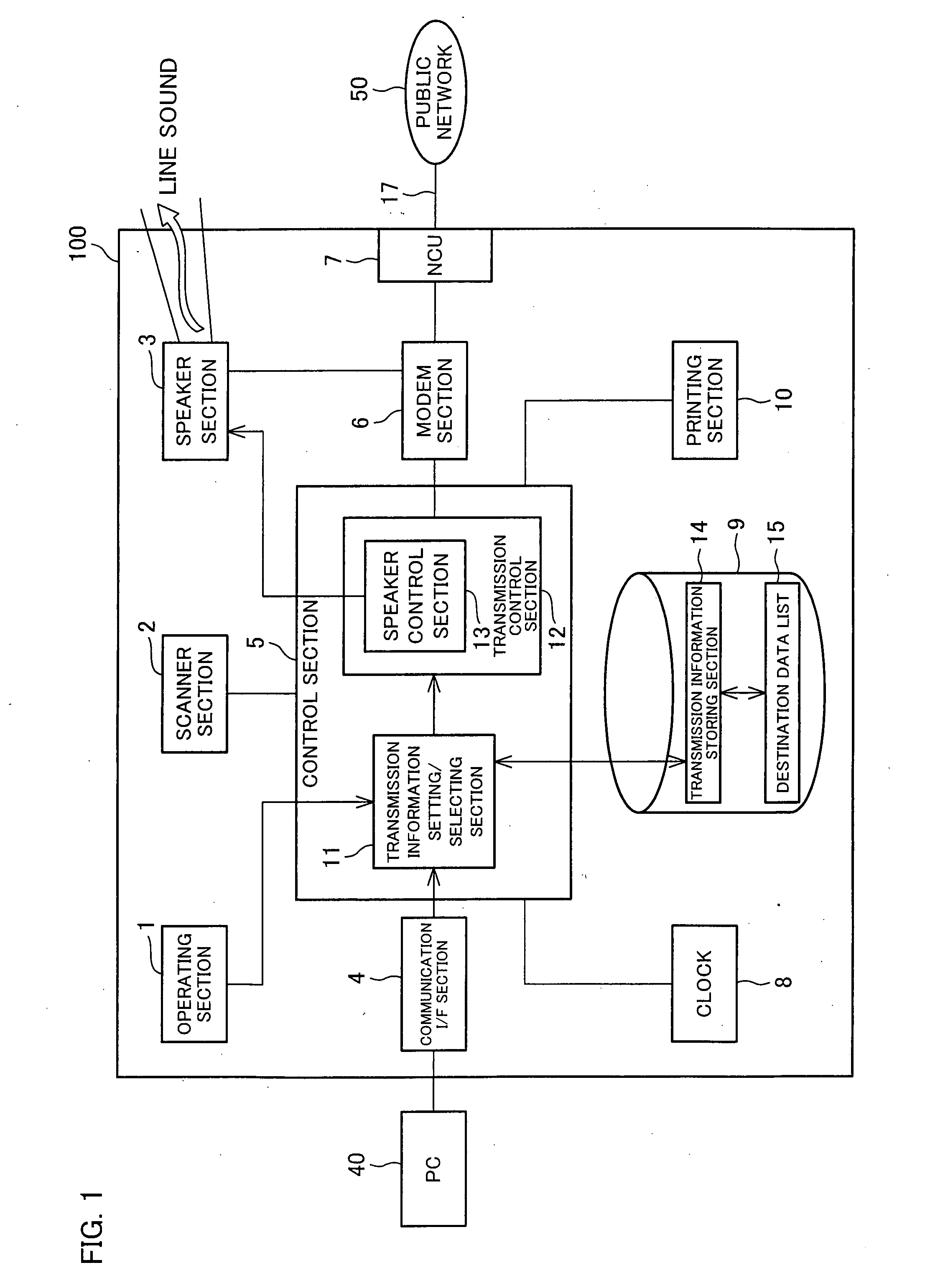
[0029] The following will explain one embodiment of the present invention on the basis of FIGS. 1 to 10.

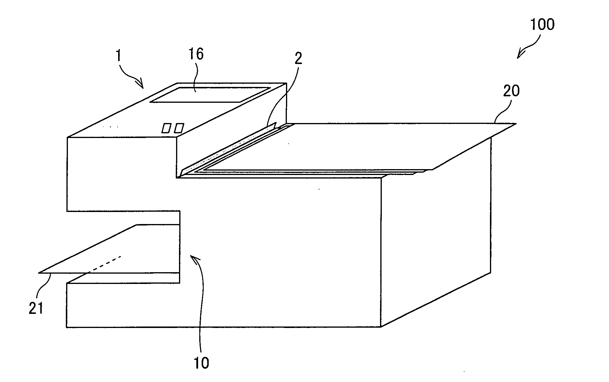
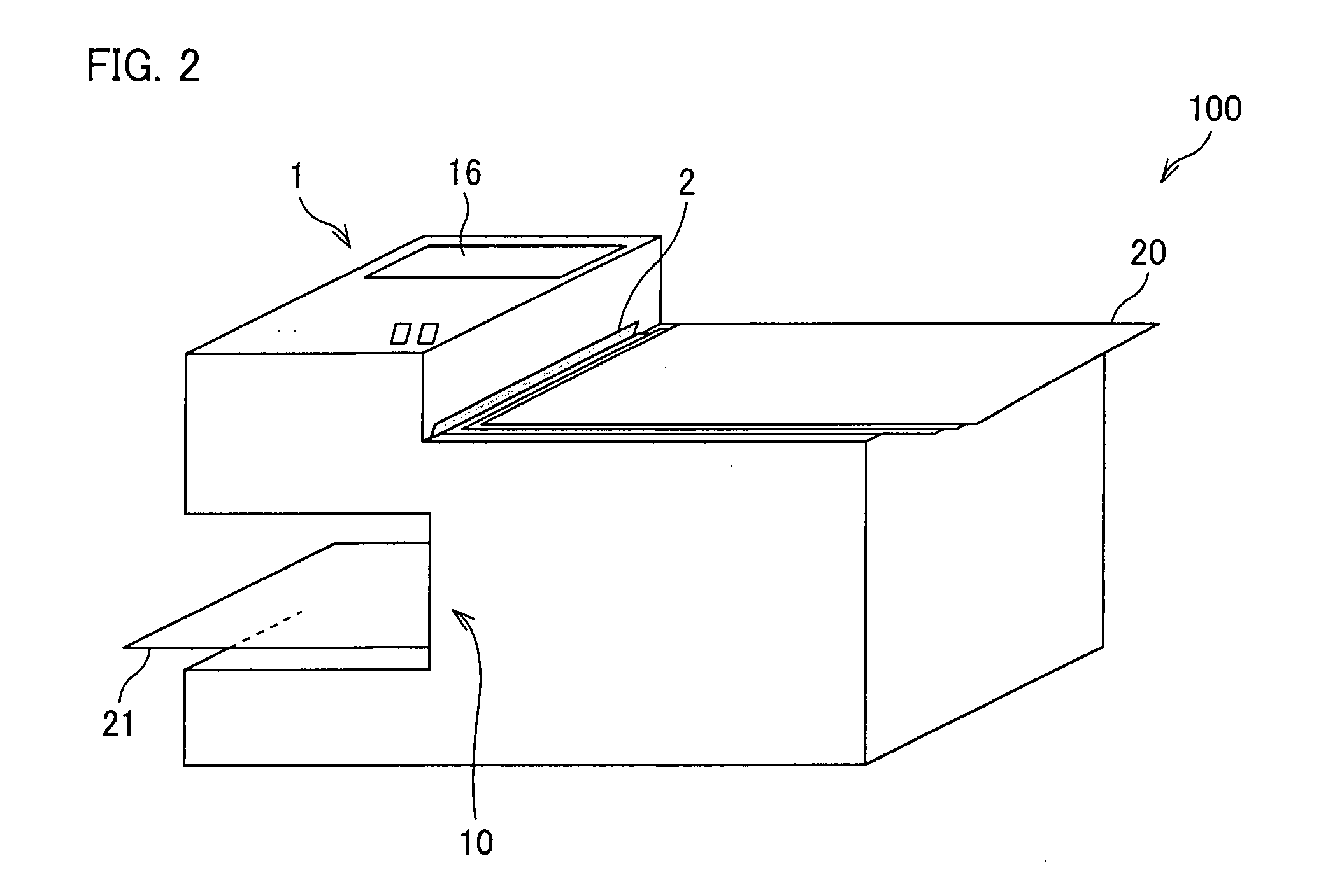
[0030] The present embodiment is explained using, as one example of a communication apparatus of the present invention, a multifunction device 100 having functions of a facsimile, a printer, a copier, etc. FIG. 1 is a functional block diagram showing a configuration of this multifunction device 100, and FIG. 2 is a perspective view showing an appearance of this multifunction device 100.

[0031] As shown in FIG. 1, the multifunction device 100 includes an operating section (acquiring section) 1, a scanner section 2, a speaker section (sound generating section) 3, a communication I / F section (acquiring section) 4, a control section 5, a modem section 6, a NCU section 7, a clock section 8, a storing section 9, and a printing section 10.

[0032] The operating section 1 allows an operator to carry out a key input to reserve or execute various settings or communication processings. The s...


PUM


Abstract

A multifunction device (communication apparatus) (100) includes (i) a transmission information storing section (14) which associates line sound information indicating whether to emit a line sound that is a sound indicating a communication signal generated at the time of data transmission with a destination number specifying a destination of data and stores the line sound information and the destination number, (ii) a transmission control section (12) which controls data transmission to the destination on the basis of the destination number, (iii) a speaker section (sound generating section) (3) which emits the line sound, and (iv) a speaker control section (line sound control section) (13) which controls whether or not the speaker section (3) emits the line sound on the basis of the line sound information. With this, it is possible to change whether to emit the line sound in accordance with, for example, the destination.

Description

TECHNICAL FIELD [0001] The present invention relates to a communication apparatus, such as a facsimile. BACKGROUND ART [0002] Generally, most facsimile equipments having an autodial FAX transmission function have the so-called dual-access function to improve work efficiency. The dual-access function is such a function that, even while the facsimile equipment is carrying out a transmission operation and / or a reception operation, it is possible to carry out an operation, such as a reservation of transmission to a destination, without waiting for the termination of the transmission operation and / or the reception operation. Its one example is disclosed in Japanese Unexamined Patent Publication No. 8-46737 (Tokukaihei 8-46737, published on Feb. 16, 1996). [0003] In the case of utilizing this dual-access function, a transmission document read by a scanner is once stored in a memory. Then, when the foregoing transmission operation and / or reception operation are (is) terminated and the line...

Claims


Application Information

Patent Timeline
IPC IPC(8): H04N1/00
CPCH04M1/82H04M11/066H04N1/00405H04N2201/0094H04N1/32037H04N1/3209H04N1/00488
Inventor HANAFUSA, HIROAKI
Owner SHARP KK
Why Eureka
Eureka Blog
Learn More