Zoom lens and imaging apparatus

a technology applied in the field of zoom lens and imaging apparatus, can solve the problems of difficult control of the prism, and achieve the effects of reducing the diameter of the lens, reducing the difficulty of image blurring, and suppressing the fluctuations of various aberrations

Inactive Publication Date: 2007-12-20
SONY CORP
View PDF1 Cites 13 Cited by
  • Summary
  • Abstract
  • Description
  • Claims
  • Application Information

AI Technical Summary

Benefits of technology

[0027] According to the present invention, it is possible to correct for image blurring caused by hand movements and the like, while s

Problems solved by technology

As described above, when a variable angle prism is located right before the lens system, there is an issue in that proper control of the prism is difficult since the deflection angle of the prism that is required for the correcting of image blurring that is caused by camera movements is indepe

Method used


Image

  • Zoom lens and imaging apparatus
  • Zoom lens and imaging apparatus
  • Zoom lens and imaging apparatus

Examples


embodiment 1

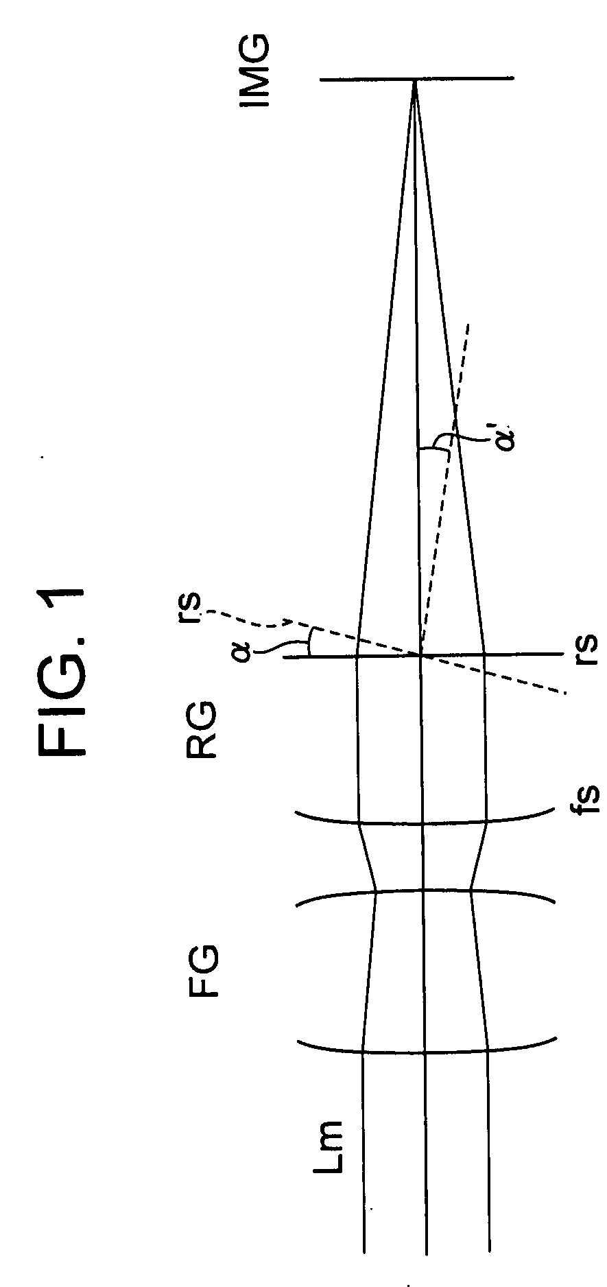
[0057] Regardless of the lens position state, the rear group is fixed in the direction of the optical axis, and the following conditional Equations are satisfied:

1fp / Bf<3   (1)

3<Bf·FNO / Ymax   (2)

where fp is the focal length of the positive lens provided within the rear group, FNO is the F number in the maximum telephoto state, and Ymax is the maximum image height.

embodiment 2

[0058] The following conditional Equation is satisfied:

0.2<Ymax / Rn<0.7   (3)

where Rn is the radius of curvature of the object side lens surface of the positive lens provided within the rear group.

embodiment 3

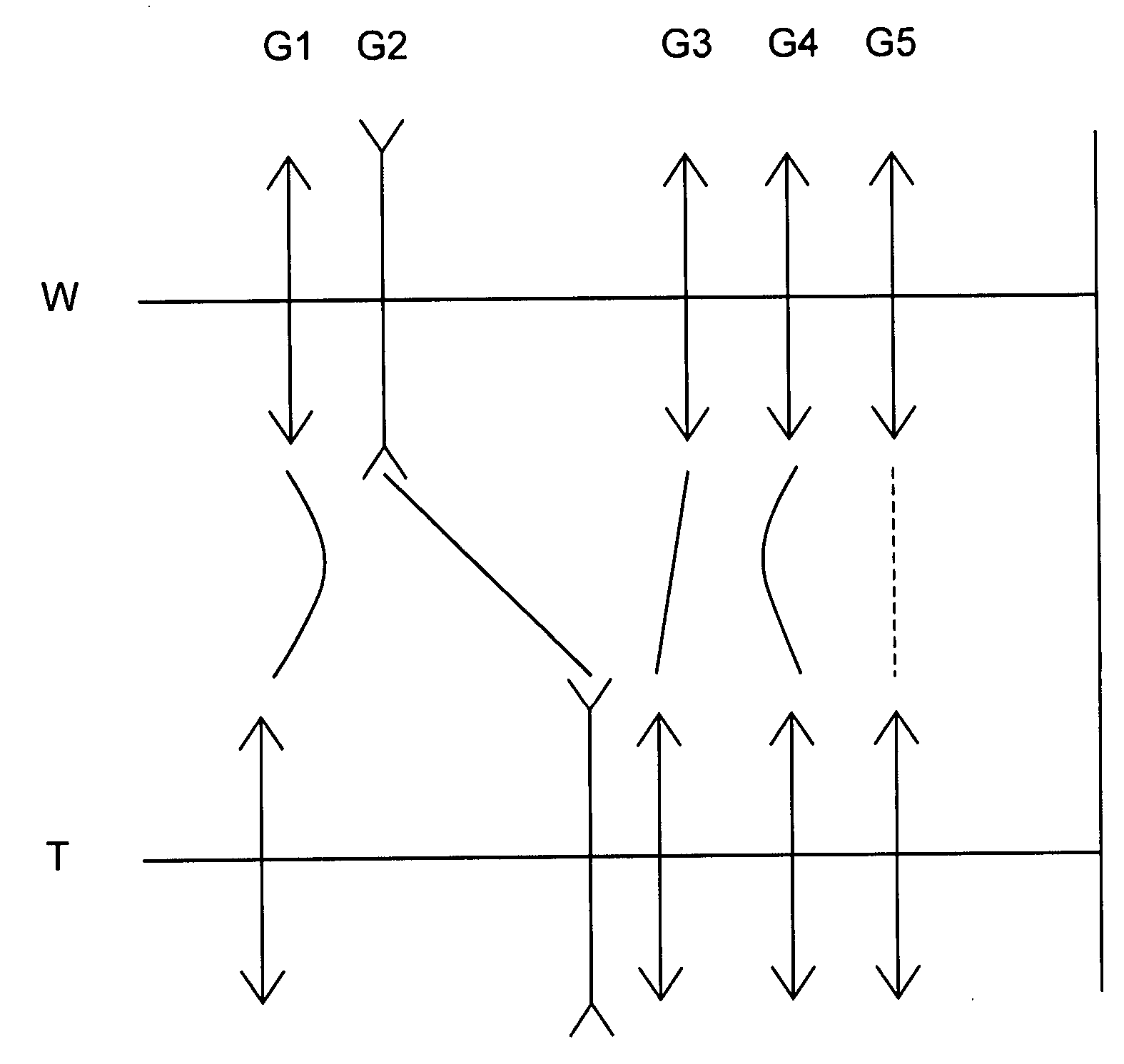
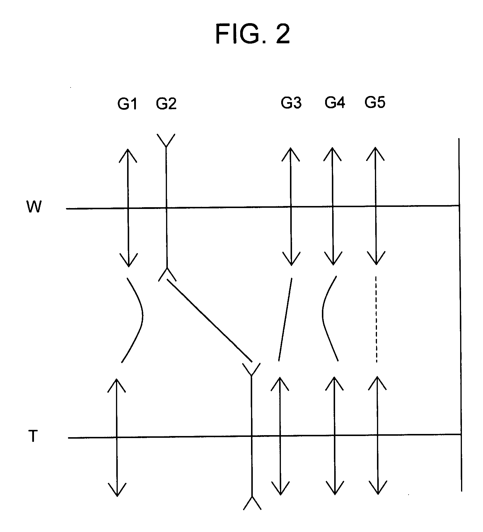
[0059] An aperture stop is provided within the front group, and the front group includes at least one movable lens group on both the object side and image side of the aperture stop. The focal length varies as the movable groups move, and the following conditional Equation is satisfied:

0.4<Ds / TL<0.7   (4)

where Ds is the distance between the aperture stop and the image plane along the optical axis in the maximum wide-angle state, and TL is the distance between the lens surface of the zoom lens that is closest to the object and the image plane along the optical axis in the maximum wide-angle state.


PUM


Abstract

A zoom lens includes: a front group including a plurality of movable lens groups; and a rear group that is provided on an image side of the front group and that includes a negative lens and a positive lens. The positive lens has a flat lens surface on its image side, and is tiltable about a spherical center of its object side lens surface that is convex on the object side. When a lens system is inclined, the positive lens is tilted in relation to the optical axis of the lens system based on: a focal length of the overall lens system; an angle of the optical axis of the lens system after being inclined in relation to the optical axis before being inclined; a distance between the image side lens surface of the positive lens and the image plane; and a refractive index of the positive lens.

Description

BACKGROUND OF THE INVENTION [0001] 1. Field of the Invention [0002] The present invention relates to a zoom lens and imaging apparatus. More specifically, with respect to a zoom lens that is capable of image shifting, the present invention relates to a technology that makes it possible to reduce the lens diameter, and that suppresses fluctuations in various aberrations that occur during image shifting. [0003] 2. Description of Related Art [0004] With a zoom lens that has a large zoom ratio, because the angle of field becomes narrow in the maximum telephoto state, there is an issue in that even the smallest hand movement or camera shake causes a significant blurring of the image. [0005] As methods of image stabilization that correct for the blurring of images caused by such hand movements or the like, optical image stabilization systems are known. [0006] With an optical image stabilization system, by combining a detection system that detects movements of the camera that accompany han...

Claims


Application Information

Patent Timeline
IPC IPC(8): G02B15/14
CPCG02B27/646G02B15/173G02B15/142
Inventor OHTAKE, MOTOYUKITANAKA, KENNAITOU, TSUTOMUTSUTSUMI, TAKUYAYANO, EIJITAKAHASHI, TATSUYUKI
Owner SONY CORP
Why Eureka
Try Eureka