VoIP voice quality remote for switch-to-switch connections

a voice quality and switch-to-switch connection technology, applied in data switching networks, frequency-division multiplexes, instruments, etc., can solve problems such as excessive bandwidth usage, difficulty in qos, and increased technology sensitiveness

Inactive Publication Date: 2007-12-20
LUCENT TECH INC
View PDF16 Cites 19 Cited by
  • Summary
  • Abstract
  • Description
  • Claims
  • Application Information

AI Technical Summary

Benefits of technology

[0010]A method and apparatus for rerouting data transmissions that sends the call to different network paths based on quality of service is provided. This disclosure will allow for the transfer of data transmissions to different network bases while maintaining the end points for the users. This method includes a seamless transfer without user intervention.

Problems solved by technology

VoIP technology is often times more sensitive than other forms of data transmission.
As such, there are numerous problems associated with VoIP technology, including Quality of Service (QoS) difficulties that are not major factors with other telephone services.
Most commonly, excessive bandwidth usage and packets being out of order contribute to poor voice transmission in VoIP.
These factors have a very minor impact on data transmission quality so the average customer may not notice the reduction in quality for strict data transmissions.
However, the average customer would likely (and indeed does) notice the drop in voice QoS when these difficulties are encountered in VoIP voice services.
In this regard, even when a relatively small amount of packets are lost or are out of order it can cause many noticeable problems such as jitter and latency, which in turn can cause echo problems and / or drop outs.
These problems render VoIP technology less desirable to the average user than POTS telephone service.

Method used


Image

  • VoIP voice quality remote for switch-to-switch connections
  • VoIP voice quality remote for switch-to-switch connections
  • VoIP voice quality remote for switch-to-switch connections

Examples


Embodiment Construction

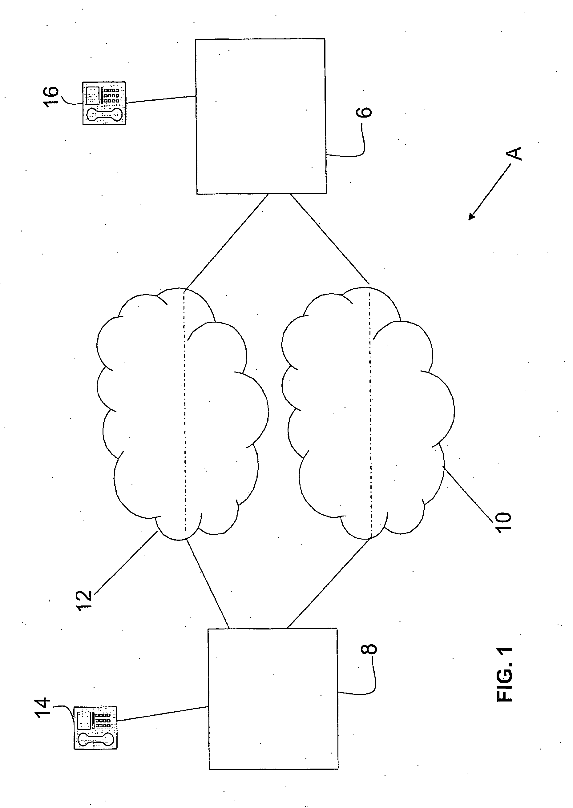
[0034]Referring now to the drawings wherein the showings are for purposes of illustrating the disclosed embodiments of the invention only and not for purposes of limiting the same, FIG. 1 provides a view of a system into which the present disclosure may be incorporated, a communications infrastructure A is shown. The communications infrastructure A includes two termination points 14, 16. Two network elements 8, 6 and two communication networks 12, 10. It should be understood that this represents but one embodiment of the communications network infrastructure A. The present disclosure could be incorporated in a variety of communication network configurations.

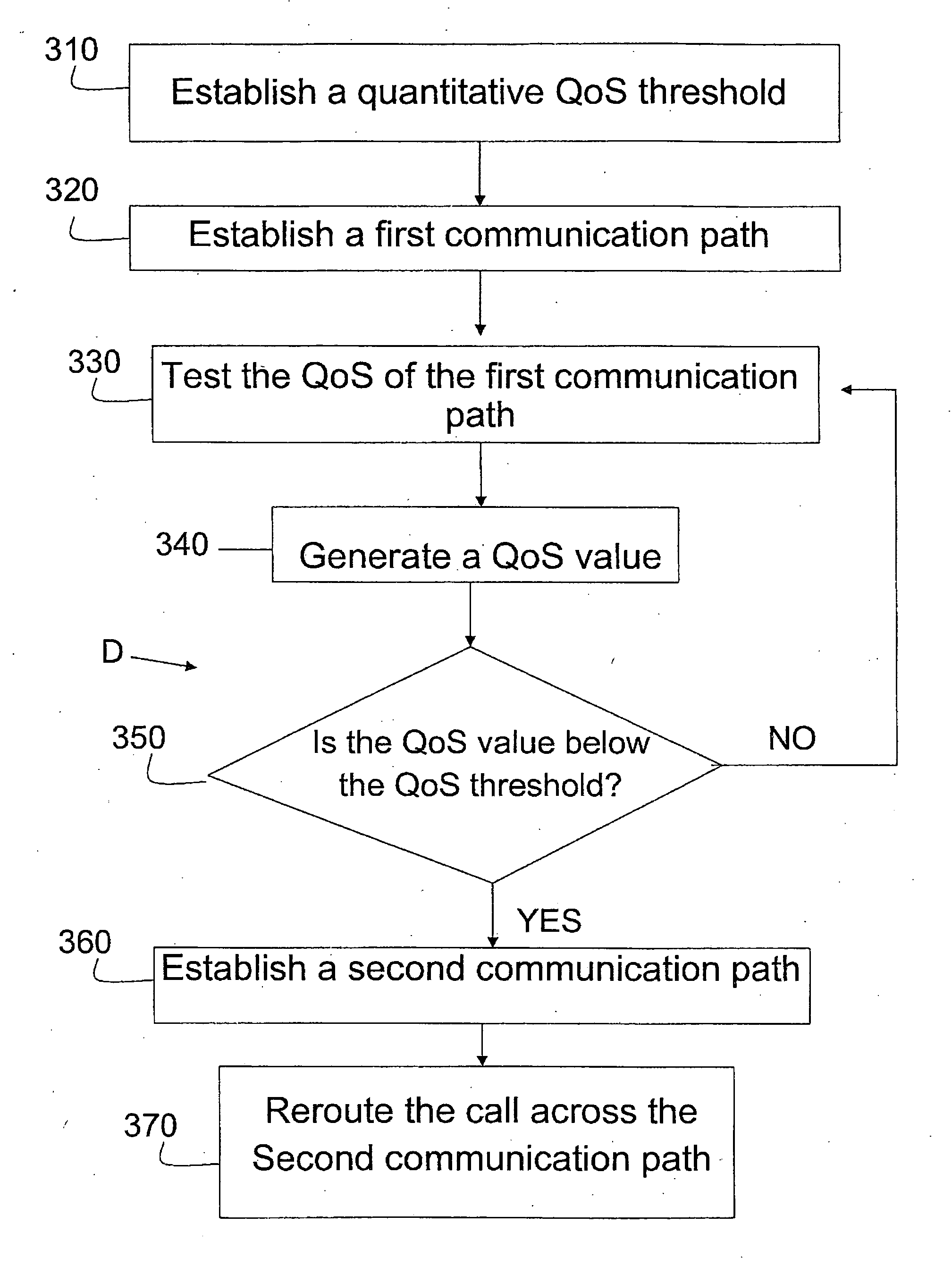
[0035]In operation, as described in greater detail below, the presently described embodiments include a method for rerouting a data transmission, such as a call. The present disclosure allows a data transmission to be rerouted with the trigger being quality of service. If the data transmission fails to meet a minimal quantitative...


PUM


Abstract

A method to reroute a call with a first and second termination point based upon Quality of Service (QoS) is disclosed. The method comprises establishing a quality of service threshold, connecting a first communication path between the two termination points through the network elements, testing said quality of service along said first communication path and generating a quantitative value based at least in part on said quality of service. The method continues with establishing a second communication path between the network elements if the quantitative value is not up to the level of said quantitative quality of service threshold; and rerouting said data transmission through the newly established second communication path between the network elements while maintaining said termination points.

Description

RELATED APPLICATION[0001]The application on which this patent is based is related to the commonly-assigned application Ser. No. 11 / 336,703 filed Jan. 20, 2006, the disclosure of which is incorporated herein by reference.BACKGROUND OF THE INVENTION[0002]This invention relates to a method and apparatus for rerouting a data transmission, such as a call. More particularly, this disclosure relates to a method and apparatus for rerouting a call to a different network path based upon quality of service while maintaining both termination points.[0003]While the invention is particularly directed to the art of voice over internet protocol (VoIP) telephony and will be thus described with specific reference thereto, it will be appreciated that the invention may have usefulness in other fields and applications. For example, the invention may be used in other types of audio and data transmission, including, but not limited to, plain old telephone service (POTS), WiFi, Wi-Max, cellular, streaming ...

Claims


Application Information

Patent Timeline
Patent Type & Authority Applications(United States)
IPC IPC(8): H04L12/26H04L12/66
CPCH04L12/2602H04L29/06027H04L41/5025H04L41/5038H04L43/00H04L43/0829H04L65/103H04L43/087H04L43/16H04L65/80H04M3/2227H04L65/104H04L65/1069H04L43/0852H04L43/55H04L65/1101
Inventor PFLEGING, GERALD W.WILKIN, GEORGE
Owner LUCENT TECH INC
Why Eureka
Try Eureka