Position-Determining and -Measuring System

a technology of positioning and measuring system, applied in image data processing, medical science, dentistry, etc., can solve the problems of high cost, high complexity and high cost of doing the job, and the use of position determination and positioning methods that are highly complex and expensiv

Inactive Publication Date: 2007-12-20
PETERS HEIKO
View PDF9 Cites 28 Cited by
  • Summary
  • Abstract
  • Description
  • Claims
  • Application Information

AI Technical Summary

Problems solved by technology

Until now, technically complex and cost-intensive methods were used for position determination and positioning in many areas of engineering and medicine.
Characteristic of all previously known navigation methods is that they either provide accurate measurement results, but are technically highly complex and expensive to do, or produce very inaccurate measurement results, but are inexpensive and technically simple.
Measuring systems with several sensors, receivers or cameras, are problematic in that when increasing the distance to the measuring points, the angle between the measuring points and sensors, receivers or cameras becomes more acute, thus diminishing measuring accuracy, and increasing effects such as movements of sensors, receivers or cameras relative to one another, e.g. due to vibrations, thus influencing measuring accuracy.
For this reason, all known techniques require very complex technical designs in order to obtain the necessary accuracy.
With regular camera- and computer-mass-production technology, such designs cannot be realized.
These technique

Method used


Image

  • Position-Determining and -Measuring System
  • Position-Determining and -Measuring System
  • Position-Determining and -Measuring System

Examples


first embodiment

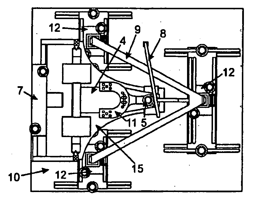
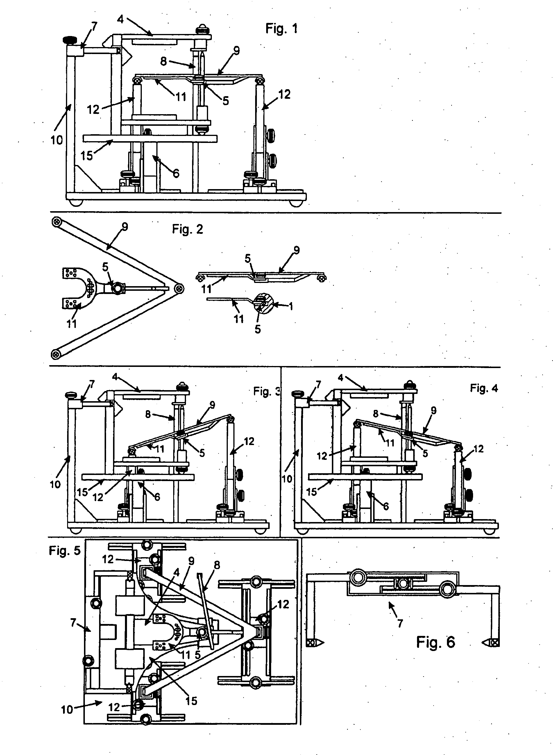
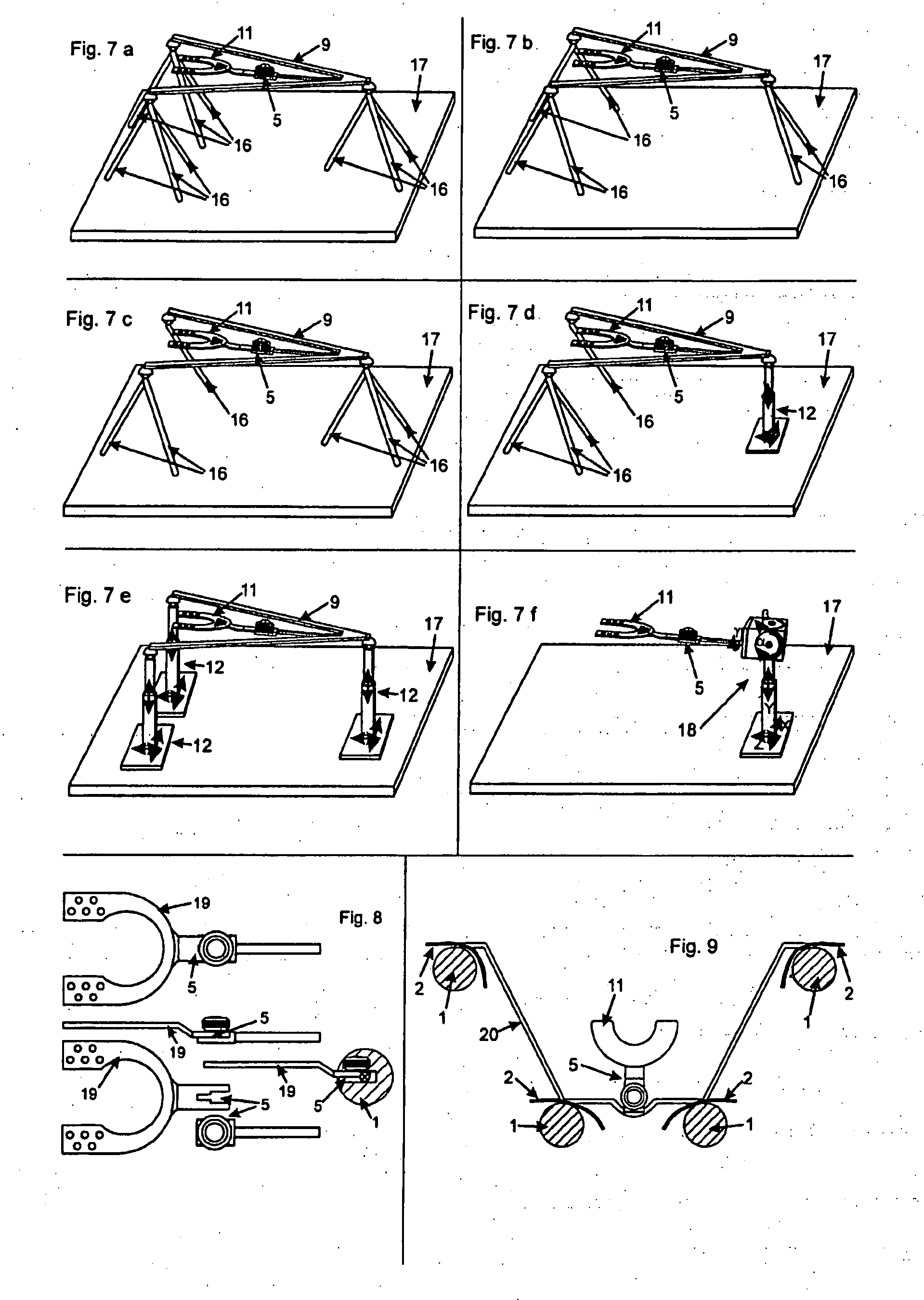
[0047] The invention may be used in dental medical applications, e.g. for instrumental functional analyses in order to determine data, allowing on the one hand adjustment of articulators in the dental medical laboratory corresponding to the patient, and on the other user decisions concerning a diagnosis and possible therapy. The assembly of dental (partial) prostheses may also be significantly simplified.

[0048] In this application of the invention, the data needed for determining condylar locations and movements are determined through optical acquisition. The data are analyzed by the program according to the invention and enable the transfer of the results in the form of data to a dentistry laboratory. The jaw models are mounted in the articulator by preferably using an apparatus according to the invention for assembling jaw models in an articulator (here referred to as a mounting table) that is set to the values determined by the program.

[0049] In this dental-medicine application...

second embodiment

of the Invention

[0079] With the method according to the invention, the position of vehicles relative to a reference point may also be determined. For this purpose, at least one optical auxiliary structure may be fixed on vehicles. One or several cameras may be fixed in the vicinity, capturing at least one vehicle, or the auxiliary structure(s). The position and especially also the alignment of at least one camera are known and represent the reference position.

[0080] Thus, when recording and analyzing images according to the method described above, the position of the vehicle may be determined.

[0081] Alternatively, a reference position may also be provided by another distinct point and not the camera. For example, in the space or environment of the vehicle, at least one further optical auxiliary structure may be fixed and represent the known reference position. The camera position then doe not need to be known.

[0082] Alternatively, at least one camera may be fixed on a vehicle and...


PUM


Abstract

The invention relates to a method for determining the position of at least one object (13, 22, 23), which is characterized in that images of at least one object (13, 22, 23) are captured by means of a single electronic camera (21). At least one optical auxiliary structure (1) is arranged on the object (13, 22, 23) to be measured or on other constructions that have a permanent spatial relationship to the object (13, 22, 23) to be measured. The measures/positions of the at least one object (13, 22, 23) in relation to the at least one reference position or a reference position which is simultaneously captured by the camera (21) are determined by evaluating the positions of the at least one auxiliary structure (1) in the captured images by means of a computer program. The invention also relates to a software and to an auxiliary transfer device which at one end comprises a coupling element (5) which allows a distinctly repositionable assembly on a face bow (20) comprising optical auxiliary structures (1) or on a device for the assembly (17) of at least one jaw model in an articulator (4) on a corresponding counterpart. The invention also relates to a device for the assembly of at least one jaw model in an articulator and to auxiliary devices for carrying out said method.

Description

[0001] The invention relates to a method for determining the position of at least one object and to a position-measuring system, software therefore, and equipment therefor. It is thus possible to determine the position of one or more objects in two- or three-dimensional space through optical capture by means of an electronic camera and evaluation of the images by appropriate image-recognition software using a computer. [0002] Determining the position of static or moving objects in real-time or based on recorded images is thus possible. PRIOR ART [0003] Until now, technically complex and cost-intensive methods were used for position determination and positioning in many areas of engineering and medicine. [0004] Examples of previously used navigation and position-measuring systems in two- or three-dimensional space are satellite navigation, distance measurements by ultrasound emitters and receivers, distance measurement by light transmitters and receivers (infrared, laser, etc.), opti...

Claims


Application Information

Patent Timeline
IPC IPC(8): G06T7/20
CPCA61C19/045G06T2207/30036G06T7/004G06T7/70
Inventor PETERS, HEIKO
Owner PETERS HEIKO
Why Eureka
Try Eureka