Band-gap voltage generator

a voltage generator and band-gap technology, applied in the direction of electrical variable regulation, process and machine control, instruments, etc., can solve the problems of complex architectures, inability to accurately and independently adjust ptat and logarithmic terms, etc., to achieve the maximum achievable accuracy

Active Publication Date: 2012-10-11
STMICROELECTRONICS SRL
View PDF3 Cites 10 Cited by
  • Summary
  • Abstract
  • Description
  • Claims
  • Application Information

AI Technical Summary

Benefits of technology

[0014]Studies carried out show that it is possible to realize a generator of a voltage that varies logarithmically with temperature using a simple architecture, based on a typical differential amplifier, that may be used at the same time also as an adder.
[0016]This architecture may be used as the input stage of an operational amplifier, or as an operational amplifier, for adding the logarithmically variable voltage with a first-order bandgap voltage, without requiring further active components. This approach may allow for independently and accurately adjusting, by trimming procedures, the PTAT and logarithmic terms, in order to get the maximum achievable accuracy.

Problems solved by technology

Even if voltage fluctuations with temperature are limited in a smaller range than that of first-order bandgap voltage generators, these architectures may be complicated to realize and / or cannot accurately and independently adjust the PTAT and logarithmic terms.

Method used


Image

  • Band-gap voltage generator
  • Band-gap voltage generator
  • Band-gap voltage generator

Examples


Embodiment Construction

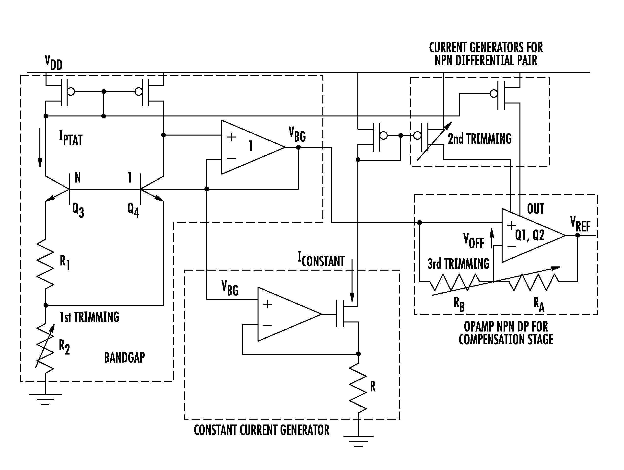
[0028]The term that compensates for the logarithmic addend in equation (1) is generated with a logarithmic voltage generator, an embodiment of which is shown in FIG. 5a. It essentially comprises a differential pair of transistors Q1 and Q2, which are generating the voltage logarithmically varying with temperature between the control nodes thereof. One transistor Q1 is biased with a current constant with temperature Iconstant, and the other transistor Q2 is biased with a current proportional to the absolute temperature IPTAT. As may be shown hereinafter, the current IPTAT is generated in common first-order bandgap voltage generators.

[0029]The currents Iconstant and IPTAT, together with the bias current generator IBIAS, force the two transistors Q1 and Q2 of the differential pair into a conduction state. The feedback line, that in the shown example is a MOS controlled in a conduction state by the voltage on the current terminal of Q1 not in common with the transistor Q2, provides a fr...


PUM


Abstract

A generator of a voltage logarithmically variable with temperature may include a differential amplifier having a pair of transistors, each coupled with a respective bias network adapted to bias in a conduction state the transistors first and second respectively with a constant current and with a current proportional to the working absolute temperature. The pair of transistors may generate between their control nodes the voltage logarithmically variable with temperature. The differential amplifier may have a common bias current generator coupled between the common terminal of the differential pair of transistors and a node at a reference potential, and a feedback line to provide a path for the current difference between the sum of currents flowing through the transistors of the differential pair and the common bias current.

Description

FIELD OF THE INVENTION[0001]The present disclosure relates to reference voltage generators and, more particularly, to a generator of a voltage variable with temperature to a bandgap voltage generator and to a related method of generating a temperature compensated bandgap voltage.BACKGROUND OF THE INVENTION[0002]Most electronic circuits may require a stable direct current (DC) voltage reference, particularly with regard to fluctuations of working temperature for the circuits. Usually, such stable voltage reference circuits are bandgap voltage generators that are based upon the property of a bipolar transistor to produce a base-emitter voltage with well known temperature dependence.[0003]According to a theoretical analysis in the article: Yannys P. Tsividis, “Accurate analysis of temperature effects in IC-VBE characteristics with application to bandgap reference sources”, IEEE Journal of solid-state circuits, Vol. SC-15, No. 6, December 1980, pages 1076-1084, the following equation ho...

Claims


Application Information

Patent Timeline
Patent Type & Authority Applications(United States)
IPC IPC(8): G05F1/10
CPCG05F3/30
Inventor LECCE, SERGIOROSSI, MAURIZIO
Owner STMICROELECTRONICS SRL
Why Eureka
Try Eureka