
Method of aligning hardpoints in aeronautical structures

Active Publication Date: 2020-04-30
ACITURRI ENG S L U
View PDF0 Cites 7 Cited by
  • Summary
  • Abstract
  • Description
  • Claims
  • Application Information

AI Technical Summary

Benefits of technology

The present invention provides a method for assembling structures using a jig that is flexible and adaptable to the components being assembled, which improves the accuracy of the alignment of hardpoints and reduces the need for precise tolerances. This results in cost savings and improved efficiency. Additionally, the method improves the accuracy of the alignment of the hardpoints using a laser system, which avoids the need for costly guided robots. Overall, the present invention allows for the assembly tool to adapt its position to the product or structure, improving accuracy, efficiency, and cost-effectiveness.

Problems solved by technology

This has led to a considerable increase in the demand for new aircraft both for offering new lines or services and for reinforcing existing lines or services, as well as to the need to renovate fleets to replace old and / or rather inefficient or non-cost effective aircraft.
Furthermore, for the aeronautical industry this problem is compounded by the requirement of high accuracy levels.
For this reason, due to the complexity and the number of elements the end products have, the inaccuracies and deviations that build up during the processes for manufacturing the fundamental parts as they are gradually integrated into sub-assemblies until forming the aircrafts become particularly important.
These deviations often lead to the need to modify parts or change the assembly process in situ in a recurring manner to enable finishing the product, causing extremely high cost overruns and delays and rendering the costs associated with those non-conformities present in aeronautical structure assembly operations the highest of all.
For example, in the case of jigs, the first systems were based on building platforms made up of fixed devices which supported the components and acted like auxiliary assembly aid elements, where each portion of the structure of the aircraft had its own jig elements in what was known as a “dedicated tooling.” This system, however, required a lot of time and a high cost both in terms of manufacture and modification or rectification of the various elements of the jig or “master” tools as they were true pieces of craftsmanship.
Nevertheless, although this technique improved the results of earlier techniques, its cost still left a lot of room for improvement.
Nevertheless, these systems also suffer from the drawback of lacking any flexibility whatsoever, given that in order to change the positions of the devices, a laser tracker is required for getting them ready with accuracy, however this equipment is too expensive and the process for getting them ready takes too long to do in each manufacturing process.
Nevertheless, the cost of paying off the robot is once again a significant economic barrier, particularly in the case of the aerospace industry where the manufacturing output is lower compared to other industries, such as the automotive industry, for example.
Said technique, however, also suffers from the drawback that, since it is not equipped with a jig, the aeronautical structure is assembled on itself, which sometimes hinders accuracy due to the fact that the absence of rigidity does not allow performing the final tasks for attaching the different elements, such as drilling, riveting, etc., with the required accuracy.
In other words, although the method allows for very good adaptability to the product and although very high accuracy is achieved during the first assembly phase, said accuracy may be diminished in the final operations.
Specifically, given that the disclosed method is based on making the jig adaptive, i.e., flexible when being positioned, compliance of the final assembly is achieved in some cases in which the elements making up said assembly could be considered non-compliant as they are outside certain tolerance limits if they were assembled by means of other assembly techniques or methods that do not allow said flexibility.

Method used


Image

  • Method of aligning hardpoints in aeronautical structures
  • Method of aligning hardpoints in aeronautical structures
  • Method of aligning hardpoints in aeronautical structures

Examples


Embodiment Construction

[0063]In view of the mentioned drawings, and according to the numbering used, the method of assembling hardpoints in mobile aeronautical structures of the invention can be seen therein.

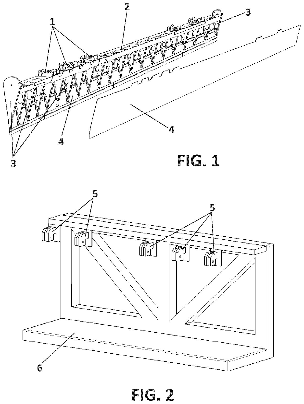
[0064]More specifically, a representative drawing of the aforementioned already known structures, which have a specific number of hardpoints (1) having their holes aligned with a very narrow tolerance as a requirement can be seen in FIG. 1. Specifically, said FIG. 1 shows a longeron (2), ribs (3), skins (4), and the mentioned fittings or hardpoints (1), among others.

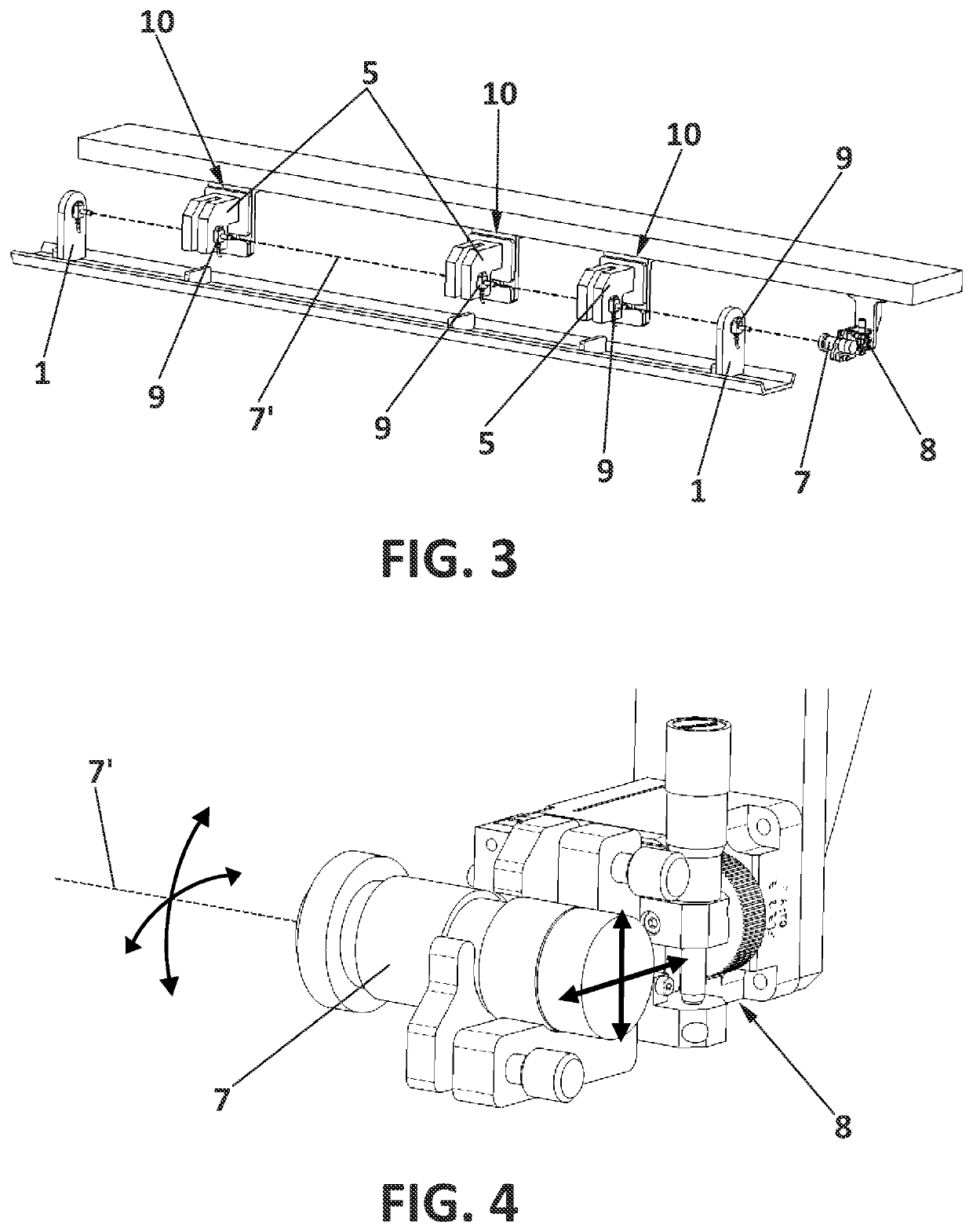
[0065]On the other hand, as can be seen in FIG. 2, the method of the invention needs a supporting structure which allows positioning the different parts or sub-assemblies making up the structure to be assembled for the correct assembly thereof, i.e., the assembly tool of the structure at hand which comprises:[0066]positioning devices or positioning elements (5) for the hardpoints, where said positioning elements (5) allow restricting one o...


PUM


Abstract

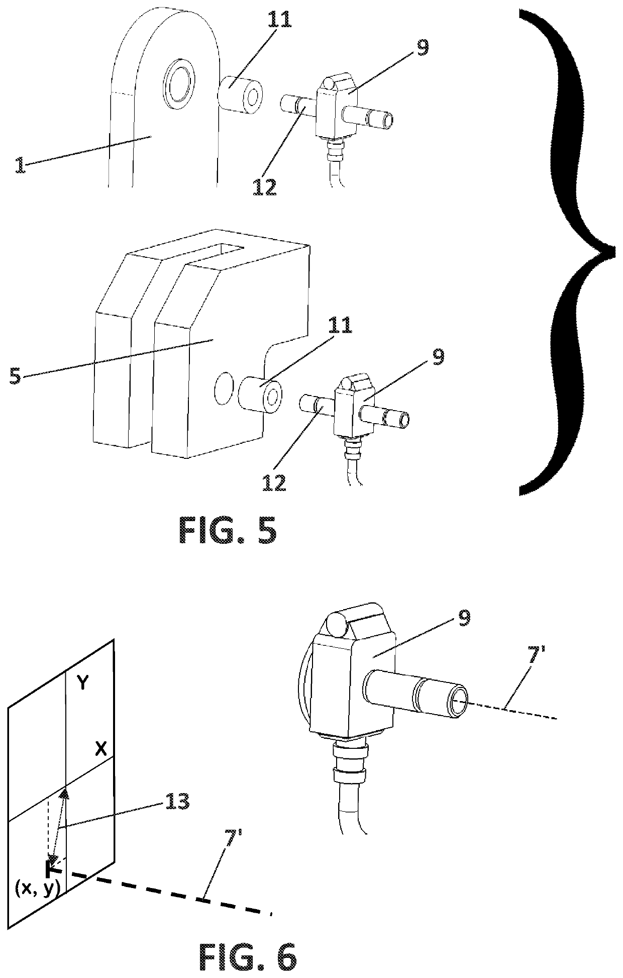
The present disclosure relates to a method of assembling hardpoints in aeronautical structures, and more specifically, the disclosed method allows knowing the relative deviation of the hardpoints and of the positioning elements of the hardpoints with respect to a laser beam emitted by a laser collimator fixed to an adjustable support which can be adjusted in at least two directions in space, and by using a correction algorithm, it is possible to know the displacement necessary for locating the positioning elements such that they are aligned with respect to the hardpoints, the positioning elements in turn being moved as a result of the movement of the driven linear tables in one or in several iterative steps, at which time the position thereof is fixed and they are ready for the rest of the hardpoints to be assembled.

Description

CROSS-REFERENCE TO RELATED APPLICATION(S)[0001]The present application claims priority to European Patent Application no 18382768.2 filed on Oct. 31, 2018, in English, the entire contents of which are hereby incorporated by reference.FIELD OF THE INVENTION[0002]The method described in the invention follows the philosophy commonly referred to as adaptive tooling, which strives for a flexible tooling that is suited to assembly circumstances and requirements for aeronautical structure.[0003]More specifically, the present invention relates to a method for assembling hardpoints that need to be aligned with one another in an aeronautical structure in a very accurate manner, where hardpoints are understood to refer to those crucially important structural parts in which other structures are assembled and through which there passes the entire, or almost the entire structural load of the assembled element, for example the attachment fittings of the elevators or rudders, ailerons, spoilers, et...

Claims


Application Information

Patent Timeline
IPC IPC(8): B23P19/10B64F5/10
CPCB64F5/10B23P19/10Y02P70/50
Inventor CIMADEVILLA GARCÍA, DAVIDBARCINA BENITO, ADRIANPALACIOS MARTÍNEZ, JAVIER
Owner ACITURRI ENG S L U
Learn More