Method of locating faults in optical telecommunication networks

a technology of optical telecommunication network and fault detection, applied in the direction of transmission monitoring, multiplex communication, wavelength-division multiplex system, etc., can solve the problems of difficult detection of fiber cut, neither of them enabling precise location of fiber cut, etc., and achieve the effect of maximum accuracy

Active Publication Date: 2007-03-06
ECE TELECOM LTD
View PDF12 Cites 9 Cited by
  • Summary
  • Abstract
  • Description
  • Claims
  • Application Information

AI Technical Summary

Benefits of technology

[0025]The fault location preferably comprises discriminating between a fiber cut occurring in a network span associated with the Network Element originating the sub-carrier detected to be absent, and between an equipment fault in said Network Element. Owing to the fact that the sub-carrier pilot tones assigned to different nodes “mark” different segments of the network, the method enables checking one local decision on the fault location by another local decision, thereby locating the fault with maximal accuracy.

Problems solved by technology

The sub-carrier signal is significantly lower in both frequency and amplitude than the main data signal so as to not impact reliable reception of the main data signal.
The problem of the above solutions is that neither of them enables precise location of a fiber cut, i.e., pointing out a specific segment of the network where a failure occurred.
The above problem, in particular, stems from the fact that any optical network comprises add-drop network elements.
Any optical carrier wavelength or a pilot sub-carrier tone may disappear just because one or more optical channels marked by them are dropped by an OADM (Optical Add Drop Multiplexer); due to that detection of a fiber cut becomes problematic.

Method used


Image

  • Method of locating faults in optical telecommunication networks
  • Method of locating faults in optical telecommunication networks
  • Method of locating faults in optical telecommunication networks

Examples


Embodiment Construction

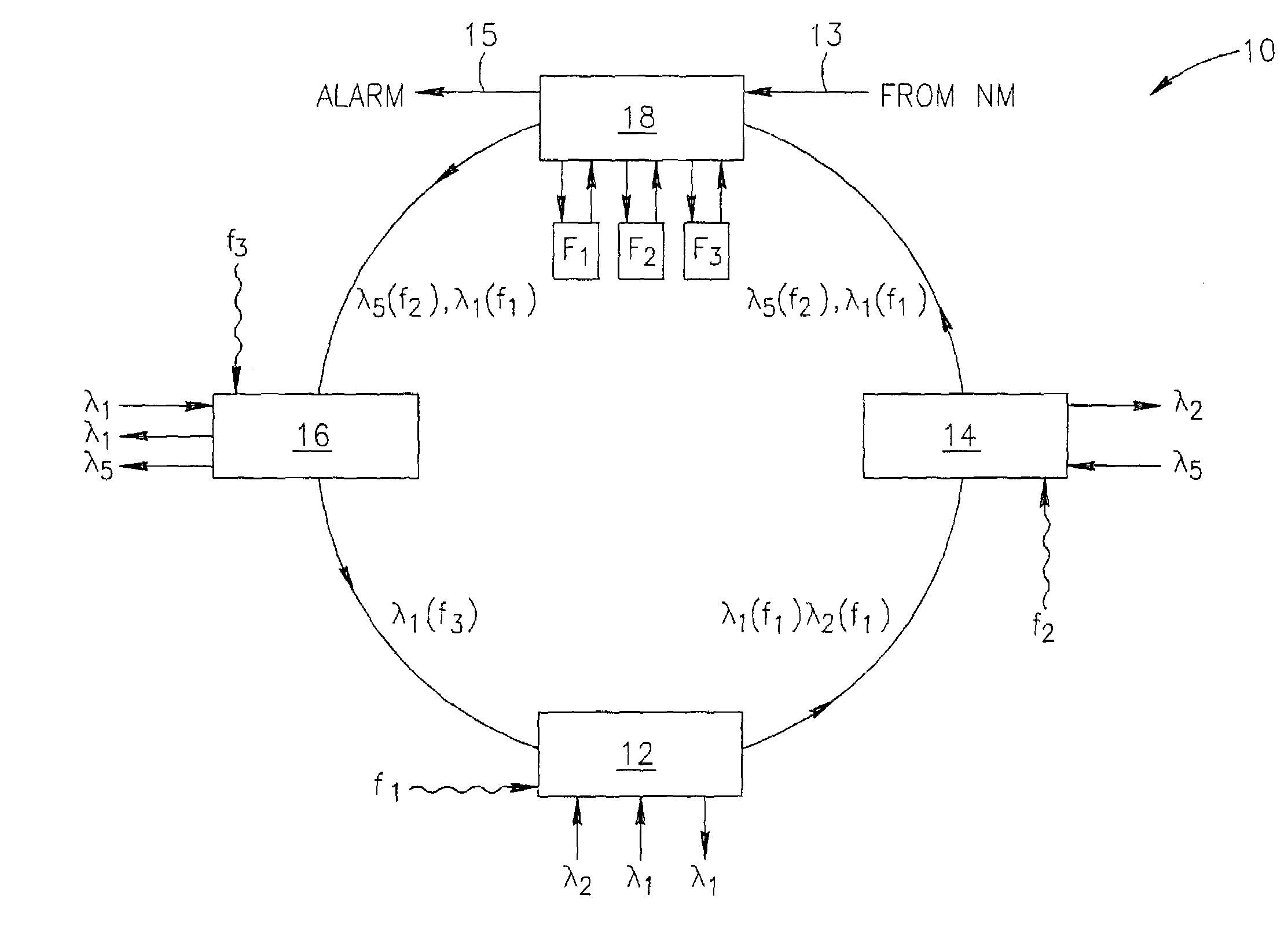
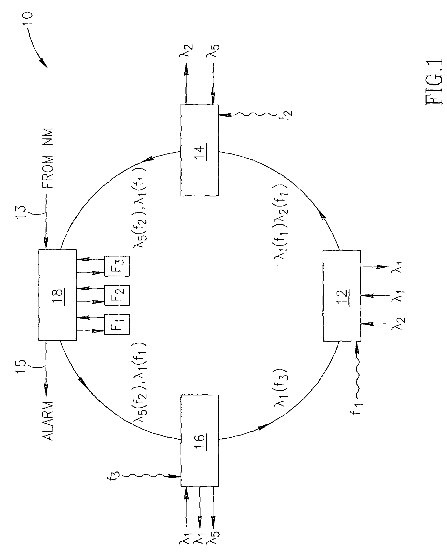
[0056]FIG. 1 shows a ring-like network 10 where each of the network nodes of interest—12, 14, 16—comprises an OADM element and is provided with an ability of impressing the added data streams with a specific sub-carrier pilot tone f1, f2 and f3, respectively. The network also comprises a checking unit 18, which is illustrated as a stand-alone device.

[0057]In this exemplary embodiment, the unit 18 is provided with filters F1, F2, F3 which are capable of detecting whether any particular pilot tone exists on the span. The unit 18 will be able to serve as a fault detecting / locating one, if it receives from a Network Manager system (not shown) information called a correct network picture. In other words, the unit 18 is informed (arrow 13) whether any of the pilot tones should exist at this particular point and, using this information, decides whether there is a fault and where (alarm 15 being a local decision). The alarms can be forwarded to the Network Manger. For example, if a sub-carr...


PUM


Abstract

A method, a system and a module are proposed for detecting and locating faults in an optical multi channel network composed of network nodes. The method includes assigning different sub-carrier pilot tones to a number of the nodes comprising Network Elements (NE), applying the different sub-carrier pilot tones to any signal added to the network via the respective nodes, checking presence of one or more of the sub-carrier pilot tones at one or more points of the network, and, based on results of the checking, locating a faulty section of the network in case a fault occurred.

Description

FIELD OF THE INVENTION[0001]The present invention relates to a method of detecting and locating faults in optical telecommunication networks.BACKGROUND OF THE INVENTION[0002]There is quite a known principle in the art of optical telecommunication networks, to detect a fiber cut by analyzing power of a signal transmitted over the span in which the fiber cut may occur. The signal may be, for example, an optical carrier wavelength assigned to a particular optical channel, or a plurality of optical carrier wavelengths transmitted over one and the same optical fiber.[0003]According to another known approach, a pilot tone is added to the data transmitted over a fiber path in the network. Absence of the pilot tone at a particular location of the network manifests the presence of a fiber cut before this particular location.[0004]U.S. Pat. No. 6,115,154 describes a method and a system for detecting fiber cuts in an optical network regardless of the number of EDEAs (amplifiers) that are locat...

Claims


Application Information

Patent Timeline
Patent Type & Authority Patents(United States)
IPC IPC(8): H04B10/08H04B10/00H04B10/02H04B10/077H04J14/02
CPCH04B10/0771H04J14/0247H04J14/0283H04J14/0246H04J14/0227H04B2210/075
Inventor MAHLAB, URI
Owner ECE TELECOM LTD
Why Eureka
Try Eureka