Angular position sensor

a technology of angular position and sensor, applied in the field of magnetic sensors, can solve problems such as acceptable rotation error of devices, and achieve the effect of significant accuracy and accurate detection

Inactive Publication Date: 2005-11-01
ZF FRIEDRICHSHAFEN AG
View PDF6 Cites 10 Cited by
  • Summary
  • Abstract
  • Description
  • Claims
  • Application Information

AI Technical Summary

Benefits of technology

[0006]The invention concerns an angular position sensor that employs a housing, for example cylindrical in shape, which rotates about its axis. In the system of the invention, at least one pair of magnets is disposed in spaced relation on the housing at opposite ends of an axis of symmetry that is perpendicular to and intersects with the axis of rotation of the cylinder. The magnets are oriented so that their opposite poles face one another over the intervening space within the cylinder. A magnetic flux detector, for example a hall-effect sensor, is disposed at a stationary position within the cylinder and between the magnets, but is offset a predetermined fixed distance from the axis of symmetry of the magnets. This asymmetric positioning of the hall-effect sensor allows the sensor to detect the change in magnetic flux with significant accuracy as the magnets rotate with the cylinder. The flux density of the magnetic field varies nearly linearly in relation to the angular position of the offset sensor over, for example ±75°, and can be detected accurately by the sensor.

Problems solved by technology

This device had an acceptable error for rotation only over a relatively small angular distance of about ±30°.

Method used


Image

  • Angular position sensor
  • Angular position sensor
  • Angular position sensor

Examples


Embodiment Construction

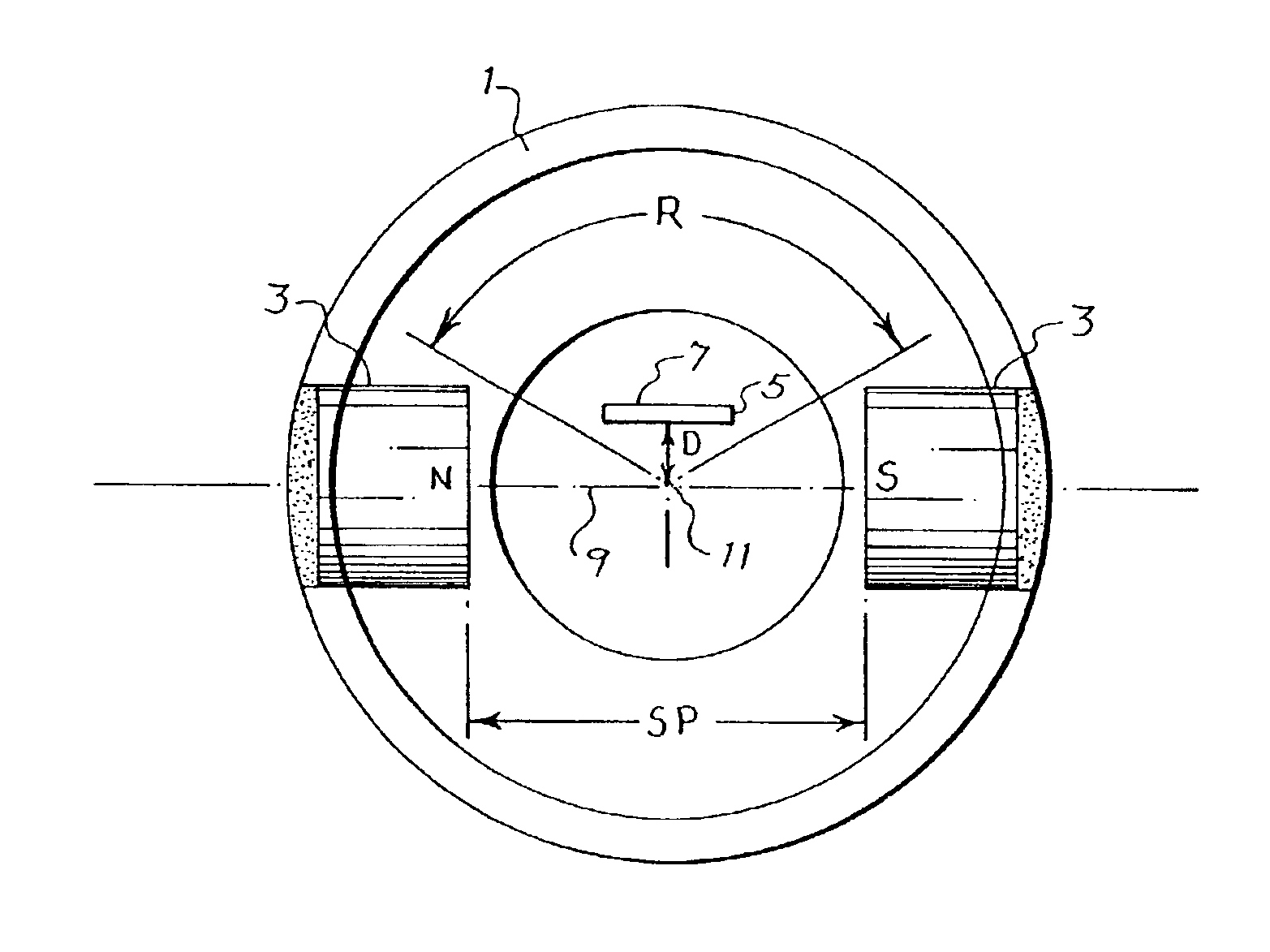
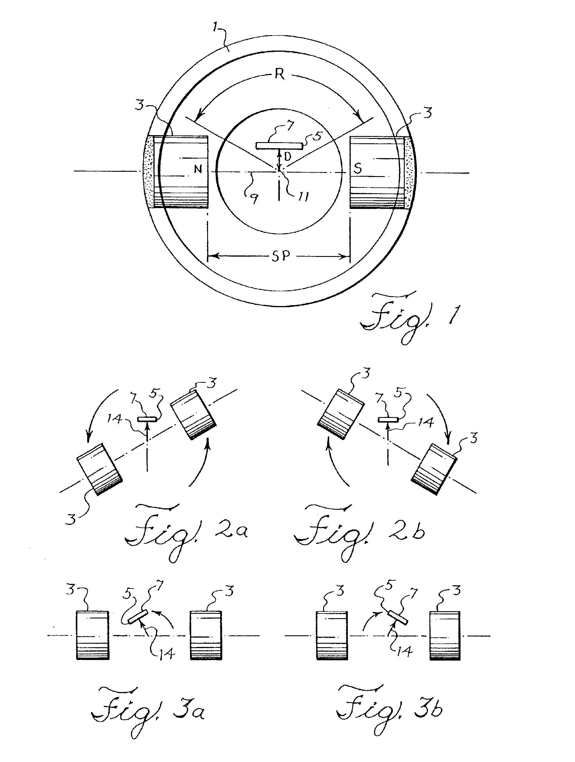
[0028]FIG. 1 is a schematic diagram of an improved angular position sensor. As shown in FIG. 1, a cylinder 1 contains a pair of opposed magnets 3 and an offset magnetosensitive detector or flux sensor 5, for example a hall-effect flux sensor or magnetoresistor, which generates electrical signals that correspond to the intensity of magnetic flux detected normal to the top sensing face 7 of the device. Magnetosensitive devices having a different detecting orientation would have correspondingly different offset orientations.

[0029]The magnets 3 are affixed to the cylinder 1 with their opposite north (N) and south (S) poles facing one another. An imaginary line 9 of geometric and magnetic symmetry passes through the axis of rotation 11 of the cylinder 1 and connects the faces of the magnets. The line 9 lies on the diameter of a circular cross-section of the cylinder 1. The disposition of the magnets is therefore symmetrical with respect to the line 9 and axis 11 of rotation of the cylind...


PUM


Abstract

An angular position sensor employs a pair of magnets that are disposed on a rotating cylinder at opposite ends of a diameter of the cylinder. A hall-effect flux sensor is fixed within the cylinder and offset from a line of geometric and magnetic symmetry between the magnets. The offset sensor detects a linear change in flux of the magnets as the magnets rotate with the cylinder over a predetermined angular distance and thereby determines the angular position of the cylinder. The offset of the sensor is adjusted to reduce the sensing error.

Description

BACKGROUND OF THE INVENTION[0001]1. Technical Field of the Invention[0002]The invention concerns a magnetic sensor that is used to detect the rotation of an operating component of a machine. More particularly, the invention concerns the use of magnets and an associated magnetosensitive device such as a hall-effect sensor which detects the operational rotation of a throttle, for example as is used to control the engine of a motorcycle or automobile.[0003]2. Description of Related Art[0004]It is known that two opposing magnets may be affixed to a cylinder so that the magnets rotate in opposed orientation as the cylinder rotates on its axis. It is also known that the moving magnetic field of the magnets can be detected by a stationary magnetosensitive detector such as a hall-effect sensor that is disposed within the rotating cylinder and between the opposed magnets. The sensor detects the changing angle of magnetic flux at its upper flux sensitive face as the magnets rotate, and genera...

Claims


Application Information

Patent Timeline
Patent Type & Authority Patents(United States)
IPC IPC(8): F02D9/10F02D9/08G01D5/14G01D5/12G01B7/30F02D9/00F02D11/10F02D35/00F02D45/00G01B7/00
CPCF02D9/105G01D5/145
Inventor MATTSON, DANIEL J.JOSEPH, PETER D.
Owner ZF FRIEDRICHSHAFEN AG
Why Eureka
Try Eureka