
Limit switch

Inactive Publication Date: 2007-12-27
ZIMM MASCHENELEMENTE
View PDF16 Cites 1 Cited by
  • Summary
  • Abstract
  • Description
  • Claims
  • Application Information

AI Technical Summary

Benefits of technology

[0008] The construction according to the invention makes possible a larger switching reserve so that the tolerances for the mutual placement of the limit switch and of the trigger part can be larger.
[0009] Further, very low wear and, therefore, a long lifetime can be achieved in a limit switch according to the invention.

Problems solved by technology

Conventional limit switches of the type mentioned above have the drawback that the positioning of the trigger part relative to the limit switch may only have relatively close tolerances in order to achieve a reliable switching process.

Method used


Image

  • Limit switch
  • Limit switch
  • Limit switch

Examples


Embodiment Construction

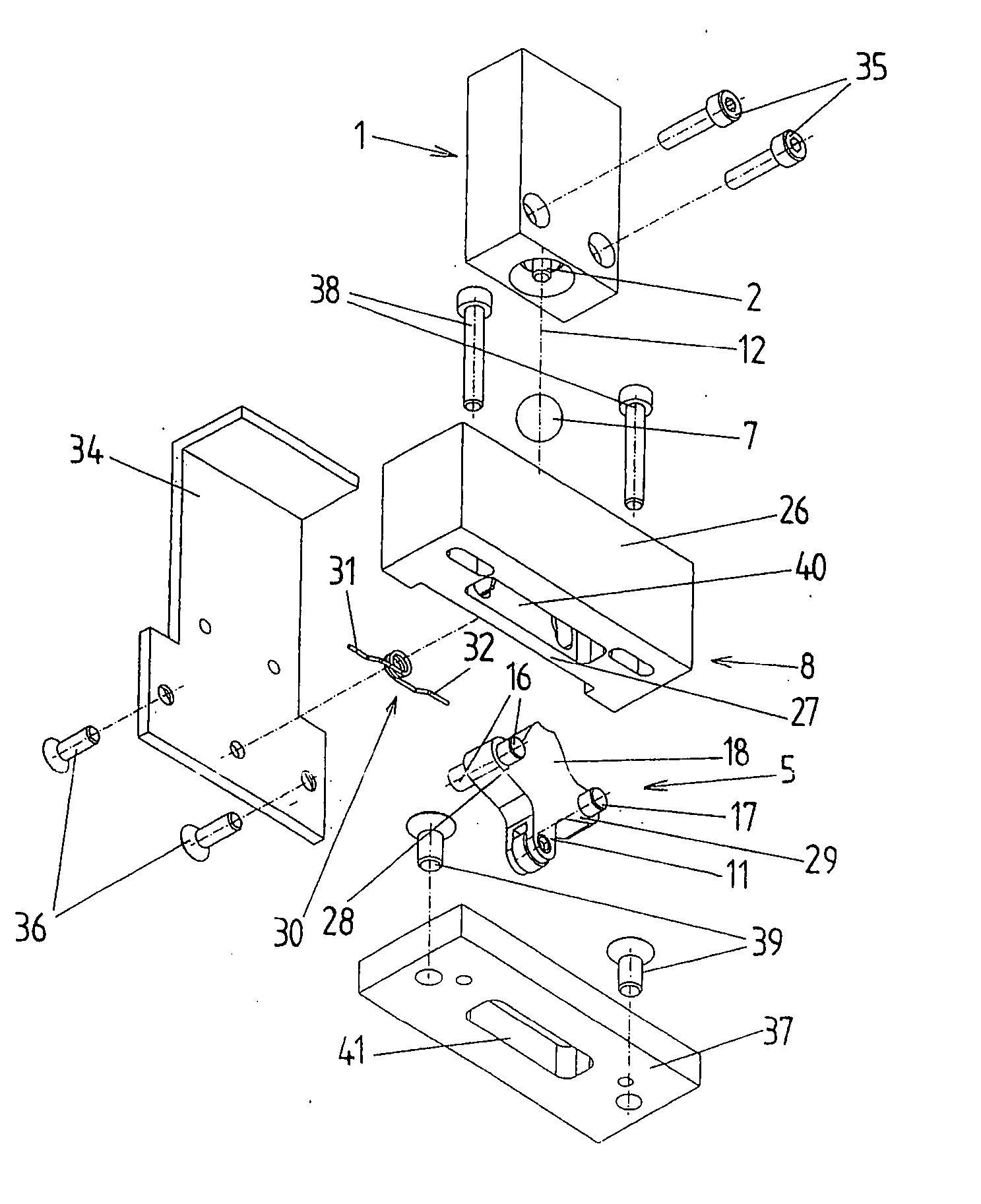
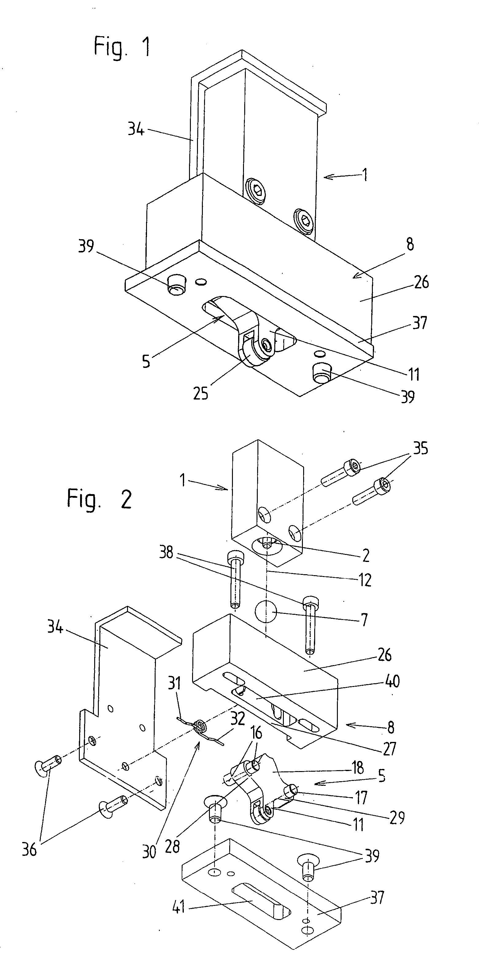
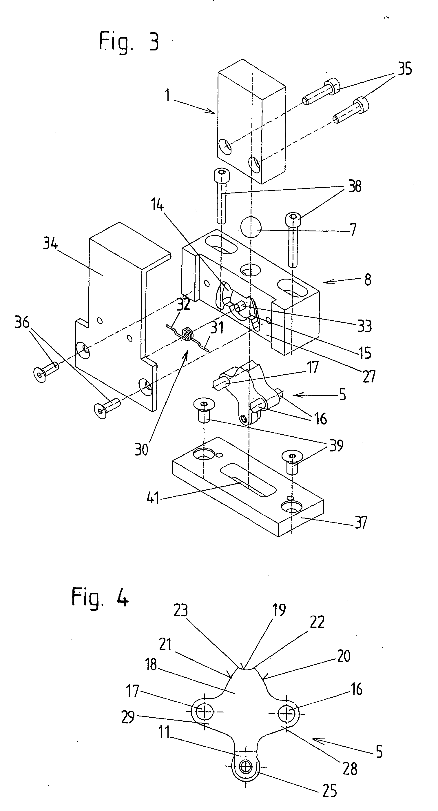
[0025] An embodiment example of a limit switch according to the invention is shown in the drawings. The limit switch has a switching part which is constructed in a conventional manner and need not be described in detail. Switching parts of this type are commercially available and are frequently used in limit switches, for example, in spindle-type lifting gears.

[0026] The switching part has an axially displaceable switching plunger 2. This switching plunger 2 serves to switch a switch contact 3 which is shown schematically in FIGS. 9 to 12. Two switching points are reached when the switching plunger 2 is displaced axially. When the first switching point is reached (see FIG. 10) when the switching plunger 2 is pressed in, the actuation of the switching contact 3 is carried out by a spring 4. This switching point is also commonly known as a “snap contact”. When the switching plunger 2 is pressed in farther than this, a second switching point is reached (see FIGS. 11 and 12). In this s...


PUM


Abstract

A limit switch comprises a switching part having an axially displaceable switching plunger for switching at least one switching contact, an actuating part by which the switching plunger is displaceable by a trigger part which runs against an actuating plunger of the actuating part transverse to the longitudinal axis of the switching plunger. The actuating part is mounted so as to be swivelable by a bearing part around a first swiveling axis and a second swiveling axis which extend parallel to one another and on both sides of the extended longitudinal axis of the switching plunger and are at a distance from the latter. The actuating part is swivelable from a basic position proceeding from the trigger part either in a first swiveling direction around the first swiveling axis or in an opposite, second swiveling direction around the second swiveling axis depending on the movement direction of the trigger part. The actuating plunger forms a first lever arm of the actuating part, and a control extension of the actuating part which forms a second lever arm of the actuating part has a control surface by which the switching plunger is axially displaceable when the actuating part swivels out of its basic position.

Description

CROSS-REFERENCE TO RELATED APPLICATION [0001] This application claims priority of Austrian Application No. A 1050 / 2006, filed Jun. 22, 2006, the complete disclosure of which is hereby incorporated by reference. BACKGROUND OF THE INVENTION [0002] a) Field of the Invention [0003] The invention is directed to a limit switch with a switching part which has an axially displaceable switching plunger for switching at least one switching contact and with an actuating part by which the switching plunger is displaceable by a trigger part which runs against an actuating plunger of the actuating part transverse to the longitudinal axis of the switching plunger. [0004] b) Description of the Related Art [0005] Limit switches of the type mentioned above are used, for example, in screw jacks or spindle-type lifting gears which serve to position a load. The movement of the spindle-type lifting gear is stopped at designated end positions by means of the limit switches. For this purpose, a trigger par...

Claims


Application Information

Patent Timeline
IPC IPC(8): H01H21/28
CPCH01H3/16
Inventor ZIMMERMANN, JUERGEN
Owner ZIMM MASCHENELEMENTE
Features
  • Generate Ideas
  • Intellectual Property
  • Life Sciences
  • Materials
  • Tech Scout
  • Unparalleled Data Quality
  • Higher Quality Content
  • 60% Fewer Hallucinations
Learn More