
Body coil and magnetic resonance imaging system

a body coil and magnetic resonance imaging technology, applied in the field of magnetic resonance imaging, can solve the problems of pin diodes generating heat, high unnecessary dc loss, etc., and achieve the effect of reducing the cost of dc power supply, reducing the loss of rf, and reducing heat loss

Active Publication Date: 2019-06-04
SIEMENS HEALTHCARE GMBH
View PDF4 Cites 0 Cited by
  • Summary
  • Abstract
  • Description
  • Claims
  • Application Information

AI Technical Summary

Benefits of technology

The present invention provides a body coil and magnetic resonance system with a lower cost of DC power supply and reduced heat generation. The invention replaces a large tuning control current with a small tuning control current, making use of an AC / DC conversion circuit capable of converting the power of an input RF emission signal to DC. This reduces RF loss and ensures a stable tuning / detuning circuit. The use of shunt inductors in the AC / DC conversion circuit allows for control of the input RF emission signal component used for conversion to DC without affecting the transmission of the input RF emission signal. The invention also simplifies the circuit structure and reduces costs by providing only one AC / DC conversion circuit and connecting all the switch diode units in parallel via RF choke inductors. Additionally, the invention allows for the use of a DC voltage signal of 0 V as the control signal, further simplifying the circuit structure and reducing costs.

Problems solved by technology

Although body coil tuning / detuning schemes commonly used at present are problem-free in terms of function, and widely applied, the high power supply current of the PIN diodes makes the cost of the DC power supply high.
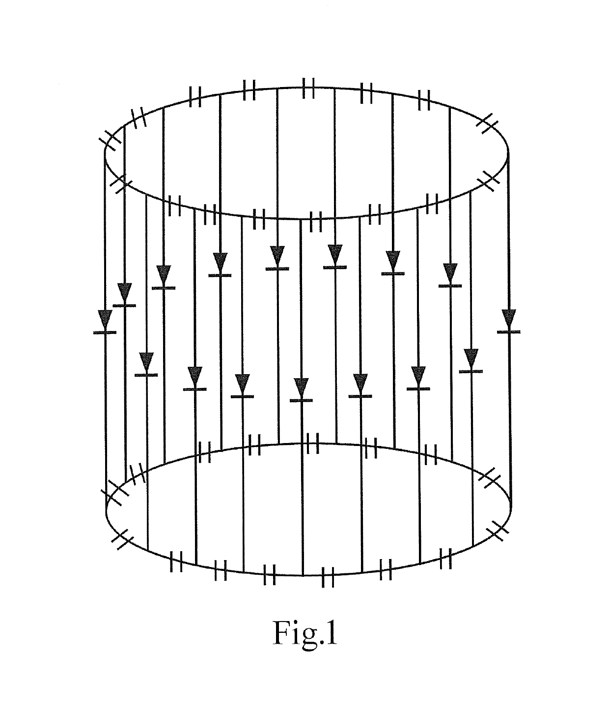
Moreover, when the body coil is in a tuned state, despite the fact that sometimes no RF energy is emitted or only a very small amount of RF energy is emitted, it is still necessary to continuously supply a DC current of 4.8, which results in an unnecessary DC loss, and is likely to cause the problem of the PIN diodes generating heat.

Method used


Image

  • Body coil and magnetic resonance imaging system
  • Body coil and magnetic resonance imaging system
  • Body coil and magnetic resonance imaging system

Examples


embodiment 1

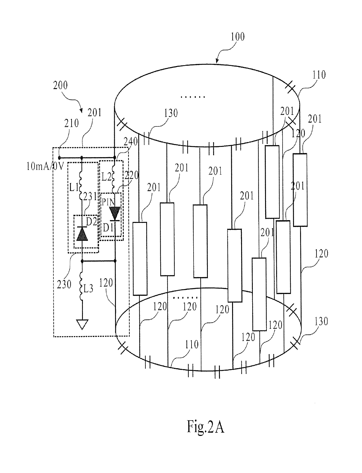
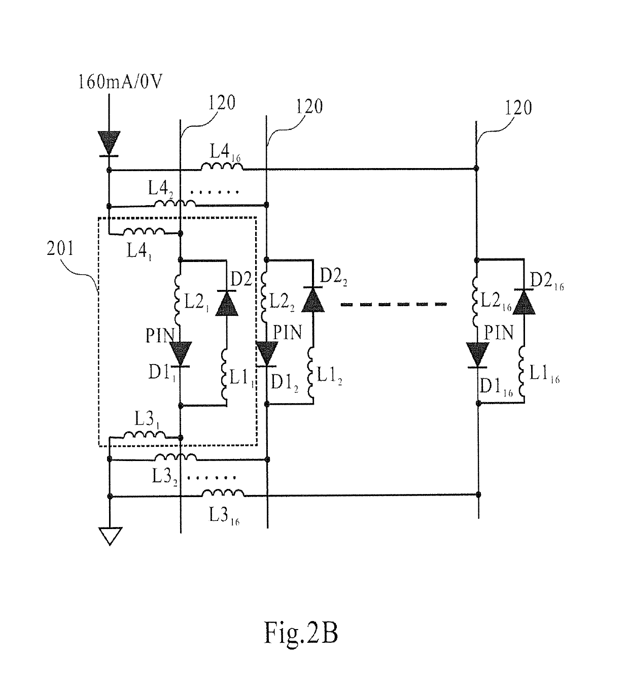
[0045]FIGS. 2A and 2B are schematic diagrams of a body coil in embodiment 1 of the present invention. FIG. 2B is a structural schematic diagram of a general control signal interface shared by the tuning / detuning circuit 200 in FIG. 2A.

[0046]As FIG. 2A shows, the body coil has a body coil conductor management 100 and a tuning / detuning circuit 200.

[0047]The body coil conductor management 100 has two end rings 110 and multiple uniformly distributed antenna rods 120 connected between the two end rings 110, as well as multiple frequency tuning capacitors 130 disposed on the end rings and / or the antenna rods. Different body coils may have different numbers of antenna rods 120, e.g. 16, 12, 8 or another number; no limitation is placed thereon in embodiments of the present invention. For convenience of description, the case where 16 antenna rods are included is sometimes taken as an example in the embodiments presented herein. In addition, although the case of the high-pass body coil shown ...

embodiment 2

[0061]FIG. 3 is a structural schematic diagram of a body coil in embodiment 2 of the present invention. As FIG. 3 shows, the body coil comprises: a body coil conductor management 100 and a tuning / detuning circuit 300.

[0062]The body coil conductor management 100 has two end rings 110 and multiple uniformly distributed antenna rods 120 connected between the two end rings 110, as well as multiple frequency tuning capacitors 130 disposed on the end rings and / or the antenna rods. Different body coils may have different numbers of antenna rods 120, e.g. 16, 12, 8 or another number; no limitation is placed thereon in embodiments of the present invention. In addition, the body coil is not limited to a high-pass body coil, but may also be a low-pass body coil or a band-pass body coil.

[0063]The tuning / detuning circuit 300 is connected to the body coil conductor management 100, and used to subject the body coil conductor management 100 to tuning / detuning control, on the basis of a control sign...

embodiment 3

[0078]FIG. 4 is a structural schematic diagram of a body coil in embodiment 3 of the present invention. As FIG. 4 shows, the body coil has a body coil conductor management 100 and a tuning / detuning circuit 400.

[0079]The body coil conductor management 100 has two end rings 110 and multiple uniformly distributed antenna rods 120 connected between the two end rings 110, as well as multiple frequency tuning capacitors 130 disposed on the end rings and / or the antenna rods. Different body coils may have different numbers of antenna rods 120, e.g. 16, 12, 8 or another number; no limitation is placed thereon in embodiments of the present invention. However, for convenience of description, the case of 16 rods is taken as an example in embodiment 3 for the purpose of description. In addition, the body coil is not limited to a high-pass body coil, but may also be a low-pass body coil or a band-pass body coil.

[0080]The tuning / detuning circuit 400 is connected to the body coil conductor manageme...


PUM


Abstract

A body coil for an MRI system has a conductor management and a tuning / detuning circuit. The tuning / detuning circuit is connected to the conductor management, and used to subject the conductor management to tuning / detuning control by a control signal. The tuning / detuning circuit has a control signal interface, a switch diode unit and an AC / DC conversion circuit. The control signal interface receives the control signal. There is at least one switch diode unit, respectively series-connected on at least one antenna rod and / or at least one end ring of the body coil conductor management. The AC / DC conversion circuit has a rectifying circuit, for converting the power of an input RF emission signal in the MRI system to a DC current, the DC current being used to provide a DC current for the switch diode unit to be turned on. The body coil reduces the cost of a DC power supply, and this reduces heat generated by the diodes.

Description

BACKGROUND OF THE INVENTION[0001]Field of the Invention[0002]The present invention relates to the field of magnetic resonance imaging, in particular to a body coil for a magnetic resonance imaging apparatus, and a magnetic resonance imaging apparatus having such a body coil.[0003]Description of the Prior Art[0004]Magnetic resonance imaging (MRI) is a modality in which the phenomenon of magnetic resonance is used to perform imaging. MRI systems generally have a superconducting magnet forming a patient receptacle, gradient coils arranged inside the superconducting magnet encircling the receptacle, a body coil located inside the gradient coils and also encircling the receptacle, an examination table on which a patient is placed, and a local coil for covering a particular part of the patient. The body coil may serve as both a transmitting coil and a receiving coil; the local coil chiefly serves as a receiving coil. The superconducting magnet provides a uniform basic magnetic field B0 in...

Claims


Application Information

Patent Timeline
Patent Type & Authority Patents(United States)
IPC IPC(8): G01V3/00G01R33/36G01R33/34
CPCG01R33/3628G01R33/3657G01R33/34076G01R33/34046
Inventor LI, WEN MINGTONG, TONGVESTER, MARKUSWANG, JIANMIN
Owner SIEMENS HEALTHCARE GMBH
Features
  • Generate Ideas
  • Intellectual Property
  • Life Sciences
  • Materials
  • Tech Scout
  • Unparalleled Data Quality
  • Higher Quality Content
  • 60% Fewer Hallucinations
Learn More