
Circuit and control method for the same

a control method and circuit technology, applied in the direction of electronic commutation motor control, mechanical energy handling, dynamo-electric components, etc., can solve problems such as efficiency degradation, and achieve the effect of improving the maximum torque of the switched reluctance motor and high load rang

Active Publication Date: 2018-10-23
TOYOTA JIDOSHA KK
View PDF3 Cites 0 Cited by
  • Summary
  • Abstract
  • Description
  • Claims
  • Application Information

AI Technical Summary

Benefits of technology

This approach enhances the maximum torque of the switched reluctance motor without degrading efficiency by selecting the appropriate winding pattern for each load condition, while also minimizing switching losses and distributing the load on the inverter.

Problems solved by technology

Therefore, if the NSNSNS winding is employed only in consideration of improving the maximum torque, there is a possibility of causing degradation of efficiency.

Method used


Image

  • Circuit and control method for the same
  • Circuit and control method for the same
  • Circuit and control method for the same

Examples


Embodiment Construction

[0036]A control device of a switched reluctance motor according to an embodiment of the disclosure will be described with reference to the drawings. The disclosure is not limited to the embodiment described below. Further, components in the following embodiment may be replaced with components that are apparent for those skilled in the art or that are substantially the same as those in the following embodiment.

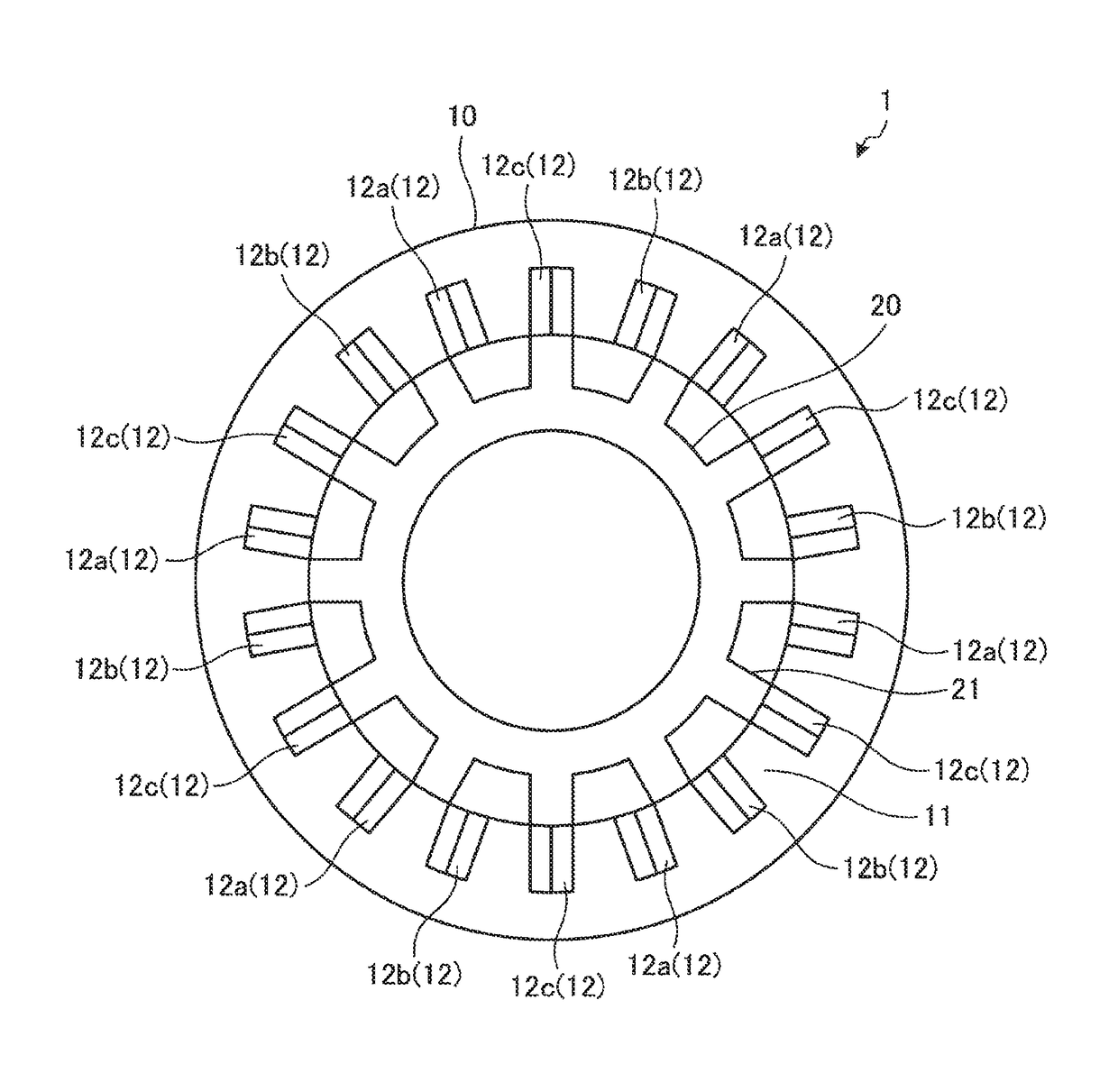
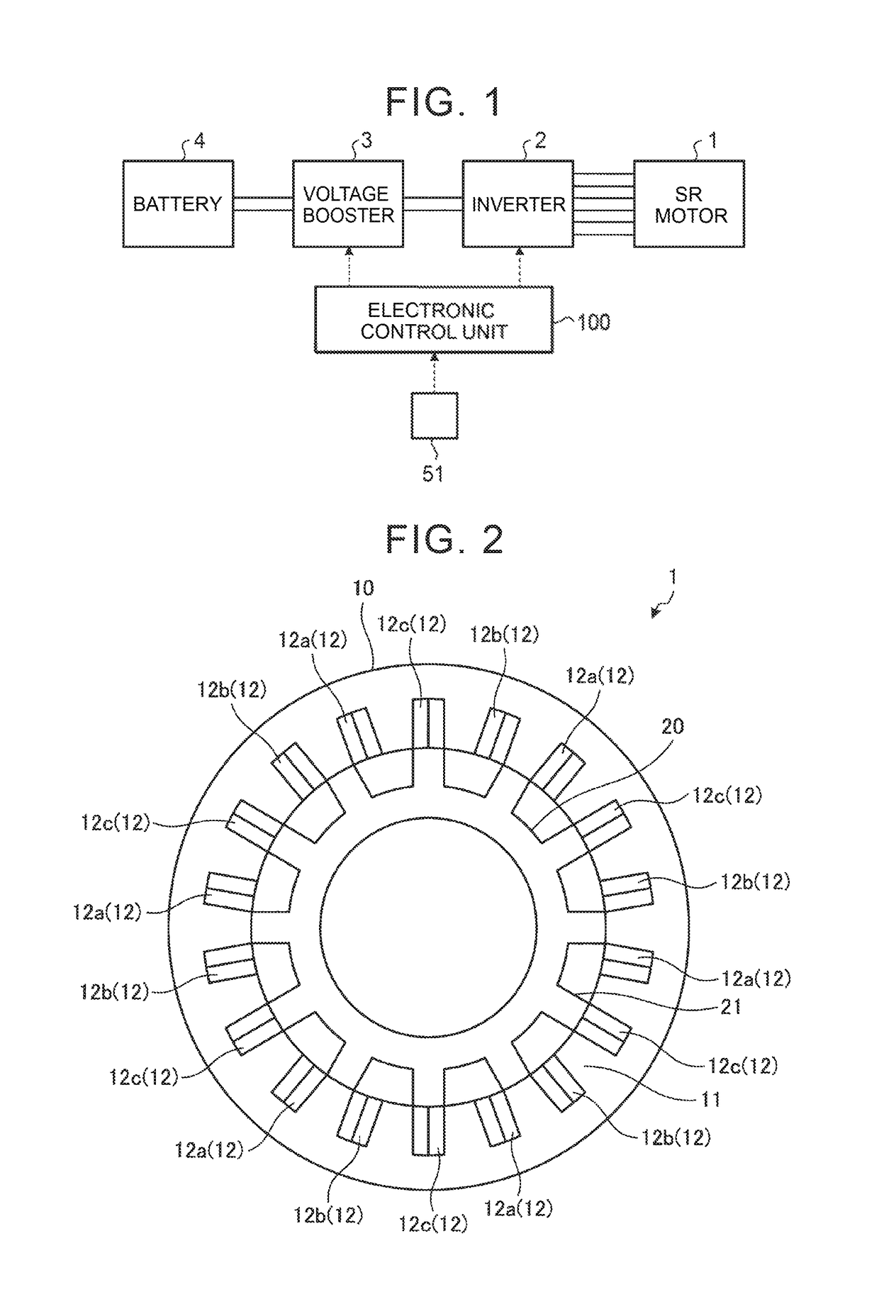
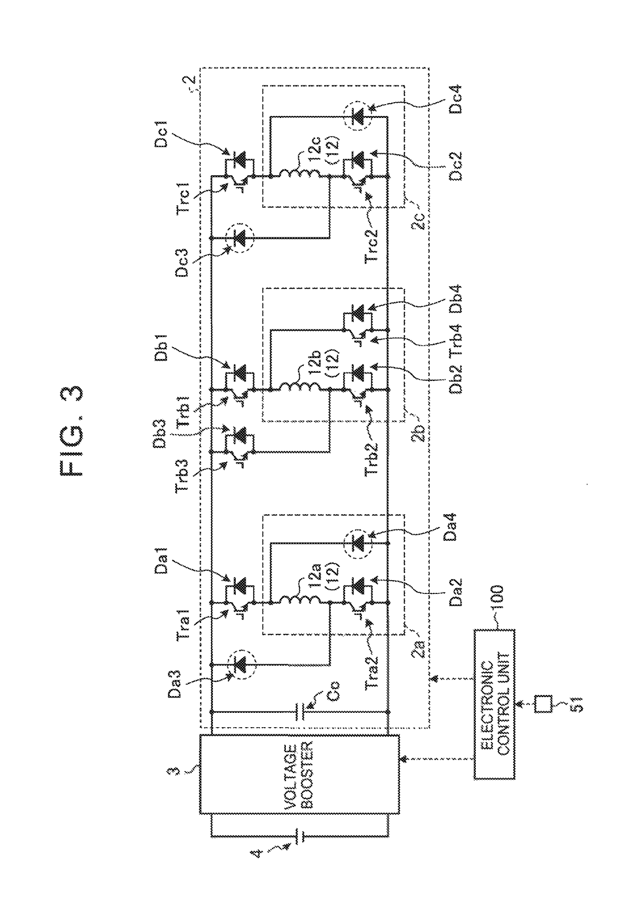
[0037]As shown in FIG. 1, the system configuration of this embodiment includes a switched reluctance motor (hereiniafter referred to as an “SR motor”) 1, an inverter 2, a voltage booster 3, a battery 4, and an electronic control unit 100. A control device of the SR motor 1 according to this embodiment includes at least the inverter 2 and the electronic control unit 100.

[0038]As shown in FIG. 1, the SR motor 1 is electrically connected to the battery 4 via the inverter 2 and the voltage booster 3. The SR motor 1 and the inverter 2 are electrically connected to each other via coi...


PUM


Abstract

An electronic control unit switches a switching circuit such that a switched reluctance motor has a first winding pattern, when, with respect to a boundary dividing a driving range of the switched reluctance motor into two ranges, a torque and a rotational speed of the switched reluctance motor that are determined according to an applied voltage are located in the first range on the low load side. The electronic control unit switches the switching circuit such that the switched reluctance motor has a second winding pattern, when the torque and the rotational speed of the switched reluctance motor are located in a second range different from the first range.

Description

INCORPORATION BY REFERENCE[0001]The disclosure of Japanese Patent Application No. 2016-163986 filed on Aug. 24, 2016 including the specification, drawings and abstract is incorporated herein by reference in its entirety.BACKGROUND1. Technical Field[0002]The disclosure relates to a circuit and a control method for the circuit.2. Description of Related Art[0003]There is known a switched reluctance motor including a stator having a plurality or salient poles, a rotor having a plurality of salient poles that are adapted to face the salient poles of the stator, and a plurality of coils respectively wound around the salient poles of the stator. The switched reluctance motor rotates the rotor by a magnetic attraction force generated between the salient poles of the stator and the rotor.[0004]In Motoki Takeno and four others, “Improvement of torque characteristic of a 50 kW SRM for HEV with a consideration of magnetic saturation of stator yoke”. The Japan Society of Applied Electromagnetics...

Claims


Application Information

Patent Timeline
Patent Type & Authority Patents(United States)
IPC IPC(8): G01R31/34H02P6/08H02P25/083H02P25/092H02K7/14H02K3/28
CPCH02P25/083H02P25/092H02P6/085H02P23/02H02P25/18H02P27/06H02P25/089H02P25/08H02P6/08
Inventor DEGUCHI, JUNICHIFUNAHASHI, MAKOTOYOSHIZUE, KENSUKE
Owner TOYOTA JIDOSHA KK
Features
  • Generate Ideas
  • Intellectual Property
  • Life Sciences
  • Materials
  • Tech Scout
  • Unparalleled Data Quality
  • Higher Quality Content
  • 60% Fewer Hallucinations
Learn More