
Method for operating several loads in alternating current networks with leading edge or trailing edge phase cutting

a technology of leading edge and trailing edge, applied in the direction of ac-ac conversion, power conversion systems, ac-ac conversion, etc., can solve the disadvantage of edge phase-angle control means and achieve the effect of reducing power and prolonging delay

Inactive Publication Date: 2014-08-07
SINGULUS TECHNOLGIES AG
View PDF3 Cites 0 Cited by
  • Summary
  • Abstract
  • Description
  • Claims
  • Application Information

AI Technical Summary

Benefits of technology

The patent describes a solution for reducing harmonic reactions on a network by driving specific half waves for both positive and negative consumers, while also improving power control range by allowing for a switch-off of specific half waves in a second operating mode. The technical effects of this solution are improved efficiency and reduced harmonic reactions on the network, resulting in improved performance and reliability of the electrical system.

Problems solved by technology

Leading edge phase-angle control means are disadvantageous in view of the non-sinusoidal shape of the current, because the current flows only in a part of the half wave.

Method used


Image

  • Method for operating several loads in alternating current networks with leading edge or trailing edge phase cutting
  • Method for operating several loads in alternating current networks with leading edge or trailing edge phase cutting
  • Method for operating several loads in alternating current networks with leading edge or trailing edge phase cutting

Examples


Embodiment Construction

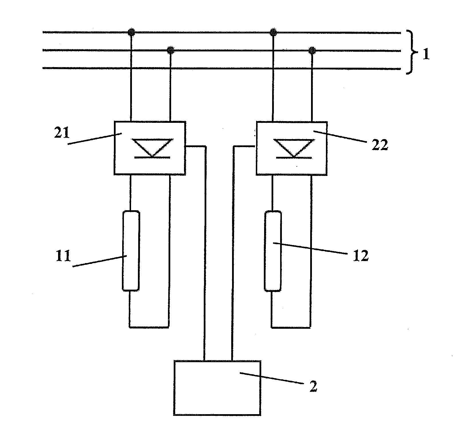
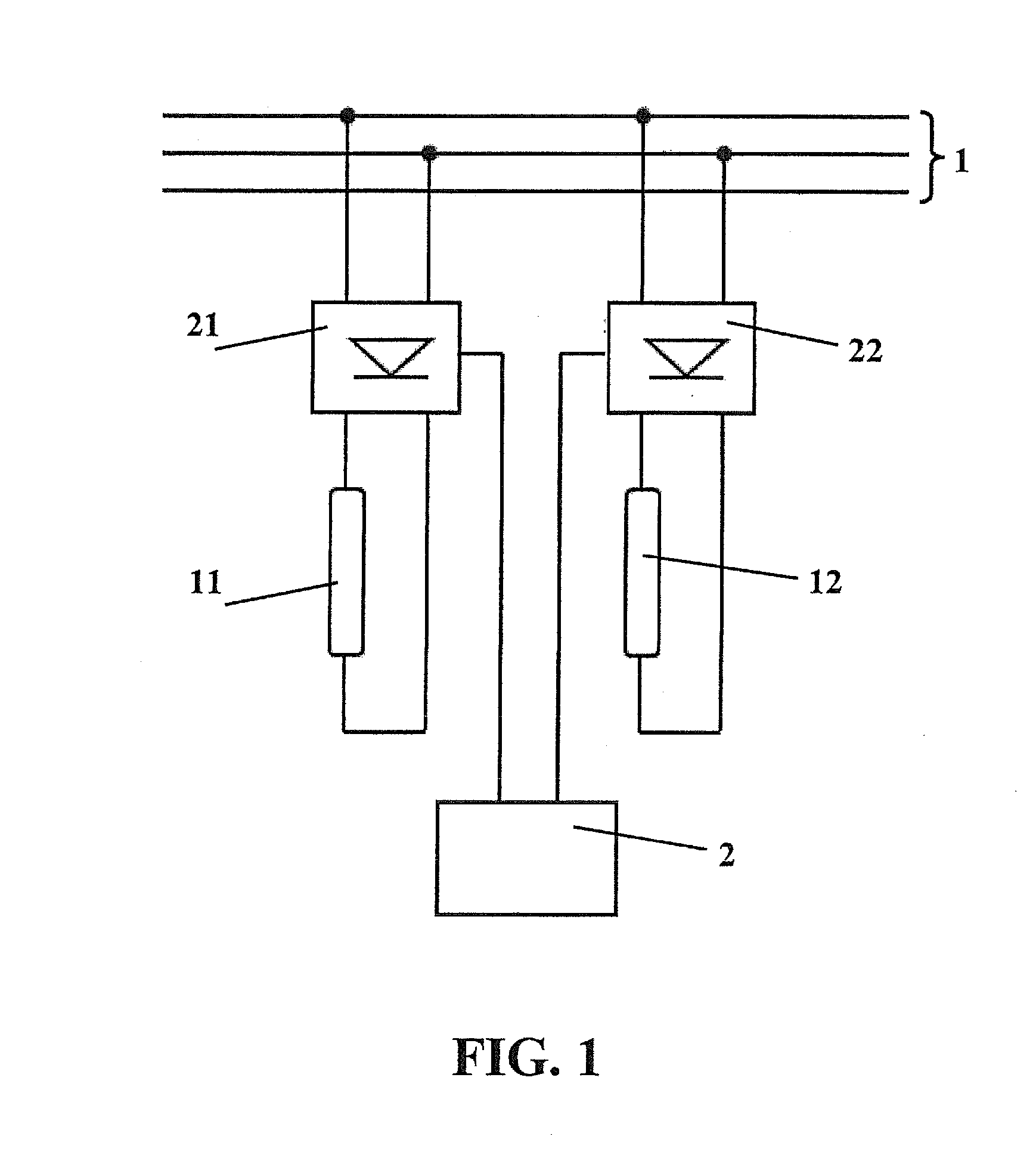
[0055]FIG. 1 shows an exemplary circuit for a device with two loads or consumers 11, 12 and two leading edge phase-angle control means (actuators) 21, 22 for controlling the current flow and an AC network 1. After the zero crossing of the AC current, the leading edge phase-angle control means delays the current flow and switches it on (“controlling” or “driving”) in case of a specific leading edge phase angle, so that the current flows until the next zero crossing. The control circuit 2 performs the controlling or driving operation. A (inverse) measure for the duration of the delay of the current flow is the leading edge phase switching, it is large in case of small leading edge phase angles and small in case of large leading edge phase angles. The consumers 11, 12 are connected in parallel and can be driven by the AC network 1. The first consumer 11 is driven by the first leading edge phase-angle control means 21, while the second leading edge phase-angle control means 22 drives th...


PUM


Abstract

A method for operating a first and a second electrical load or consumer in an alternating current network. The method can be operated in an optional first operating mode, in which the positive and negative half waves for each load are controlled with a first leading edge phase angle. In addition, a second operating mode is provided, in which a first part of the positive and negative half waves for the first load and a second part of the positive and negative half waves for the second load are controlled with respective second leading edge phase angles. Furthermore, a device for performing the method, having first and second leading edge phase-angle control for the first and second loads.

Description

BACKGROUND[0001]1. Field of the Disclosure[0002]The present disclosure relates to a device and a method for operating several loads or consumers in alternating current networks with leading edge or trailing edge phase cutting or switching.[0003]In particular, devices for producing thin film solar cells, high-power heating processes are required, wherein for optimizing the processes also control ranges with relatively low heating power should be allowed. For this purpose, i.a. leading edge phase-angle control means are used in order to heat substrates, e.g., made of glass, as homogeneously as possible.[0004]2. Discussion of the Background Art[0005]Leading edge phase-angle control means are disadvantageous in view of the non-sinusoidal shape of the current, because the current flows only in a part of the half wave. The lower the required current, the larger the leading edge phase angle (e.g. 90° to 180° corresponding to 50% to 0%) and the greater the deviation of the current's curve s...

Claims


Application Information

Patent Timeline
Patent Type & Authority Applications(United States)
IPC IPC(8): H02J3/00
CPCH02J3/00H02M1/12H02M5/2573
Inventor BECKER, WOLFGANGRUETH, EDGARKLEIN, BENEDIKT
Owner SINGULUS TECHNOLGIES AG
Features
  • Generate Ideas
  • Intellectual Property
  • Life Sciences
  • Materials
  • Tech Scout
  • Unparalleled Data Quality
  • Higher Quality Content
  • 60% Fewer Hallucinations
Learn More