Multi-function supporting rack

a multi-functional, supporting rack technology, applied in the field of supporting racks, can solve the problems of inconvenient use, more supporting elements, and more space, and achieve the effects of convenient assembly and installation, less space, and improved support

Inactive Publication Date: 2007-12-27
PIN ZUEN
View PDF13 Cites 23 Cited by
  • Summary
  • Abstract
  • Description
  • Claims
  • Application Information

AI Technical Summary

Benefits of technology

[0007]The primary object of the present invention is to provide a multi-function supporting rack t

Problems solved by technology

It is inconvenient when in use.
It requires more supporting elements a

Method used


Image

  • Multi-function supporting rack
  • Multi-function supporting rack
  • Multi-function supporting rack

Examples


Embodiment Construction

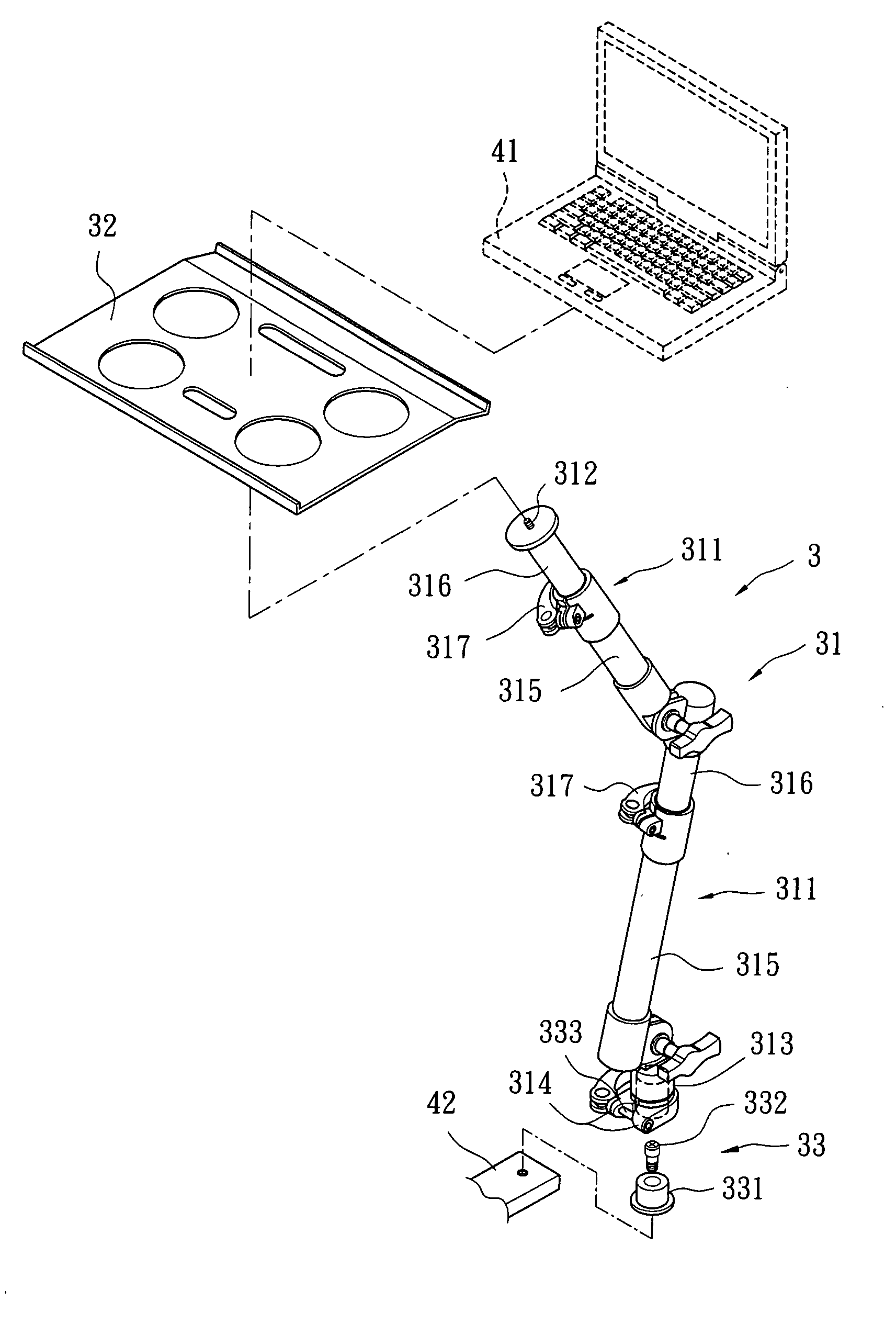
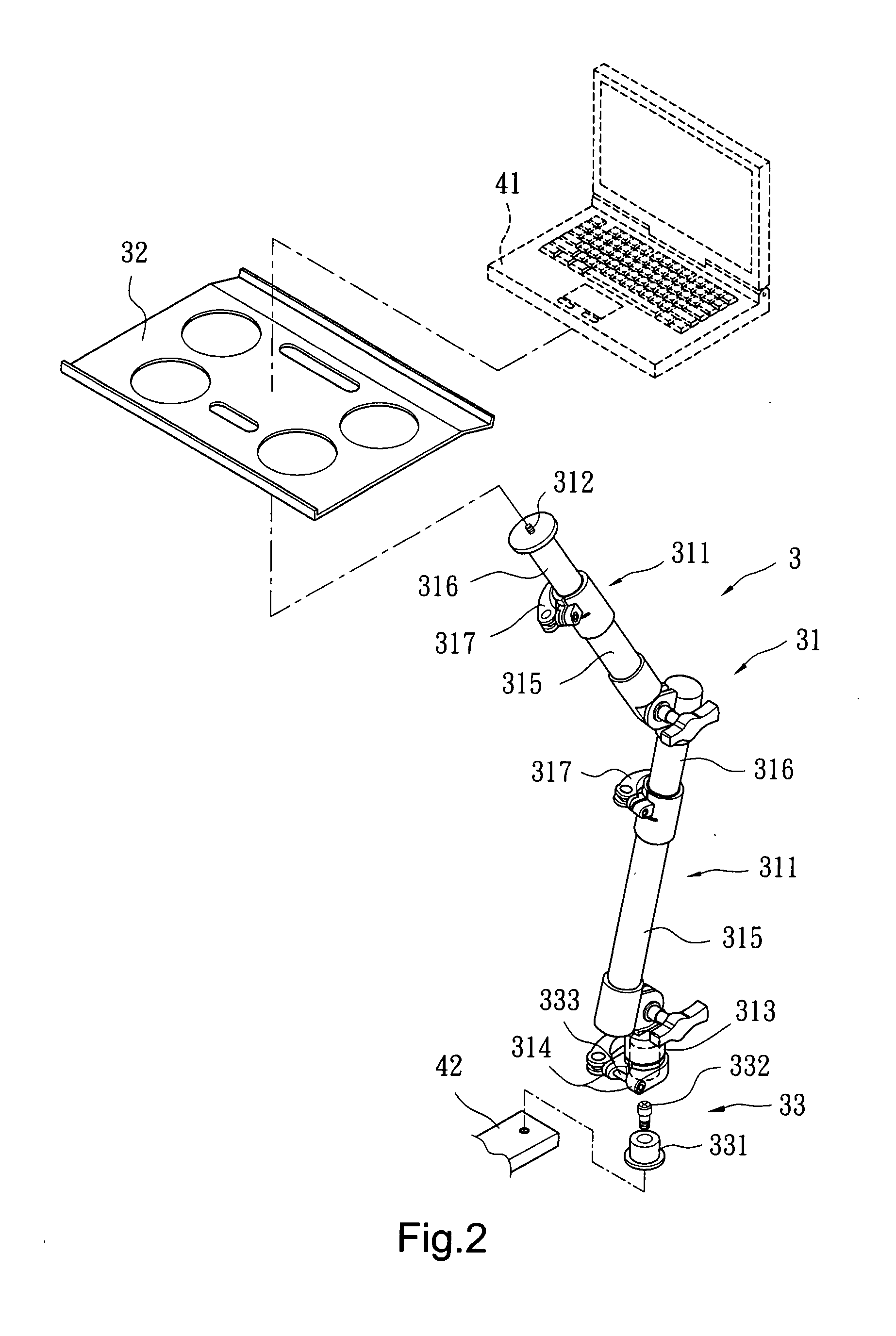
[0018]Please refer to FIG. 2 for a first embodiment of the multi-function supporting rack 3 of the invention. It is fastened to an equipment 42 to hold an article 41. It includes a rack unit 31, a holding unit 32 and a coupling unit 33.

[0019]The rack unit 31 has two bracing bars 311 pivotally coupled together, a fastening member 312 located at a top end of the upper bracing bar 311, a hollow housing portion 313 located at a bottom end of the lower bracing bar 311 and two lugs 314 located on the outer surface of the housing portion 313.

[0020]While this embodiment shows that the two bracing bars 311 are pivotally coupled together, a single bracing bar 311 may also be adopted, or two bracing bars 311 may be coupled together at a fixed angle.

[0021]Each of the bracing bars 311 has a tube 315, a movable rod 316 movable axially in the tube 315, and a clipping member 317 to anchor the movable rod 316 in the tube 315. By means of such a design the length of each bracing bar 311 can be adjust...


PUM


Abstract

A multi-function supporting rack includes a rack unit, a holding unit and a coupling unit. The rack unit has a fastening member at the top end and a hollow housing portion at the bottom end thereof. The holding unit is located on the fastening member to hold an article. The coupling unit has a latch member located in the housing portion and a connection member to couple the latch member and an equipment together. Such a design forms a greater supporting contact area between the latch member and the housing portion to provide an improved supporting effect. Moreover, once the latch member and the connection member are fastened to the equipment, the housing portion is coupled on the latch member. The finished assembly of the invention takes less space and installation is easier.

Description

FIELD OF THE INVENTION[0001]The present invention relates to a supporting rack and particularly to a multi-function supporting rack capable fastening to varying equipment to hold various types of articles.BACKGROUND OF THE INVENTION[0002]Referring to FIG. 1, a conventional supporting rack aims to hold articles such as notebook computers, photographic devices or the like (not show in the drawing) to enable users to perform photographic or computer operations. Take a notebook computer as an example. It has to be positioned at a desired elevation without being held at a lower elevation such as user's lap to make operation easier. For a photographic device, it must be held steadily without the lens wobbling due to unstable hands of users.[0003]The conventional supporting rack 1 includes two bracing bars 11 pivotally coupled together, a holding dock 12 located at the top end of the upper bracing bar 11, a main supporting member 13 located at the bottom end of the lower bracing bar 11 and...

Claims


Application Information

Patent Timeline
IPC IPC(8): A47G29/00
CPCF16M11/04F16M11/10F16M11/2021F16M2200/068F16M13/02F16M13/022F16M2200/02F16M11/26
Inventor LU, KUN-CHUNG
Owner PIN ZUEN
Why Eureka
Try Eureka