
Image display device having wide and narrow viewing angle modes and method of driving the same

a display device and wide-angle viewing technology, applied in the field of display devices, can solve the problems of not having the conversion between wide-angle viewing modes, the lcd device does not provide multi-viewing modes, and the lcd device according to the related art fails to provide sufficient privacy for users, etc., to achieve excellent lateral image blocking characteristics, enhance user privacy, and reduce cross-talk defects

Active Publication Date: 2007-12-27
LG DISPLAY CO LTD
View PDF4 Cites 9 Cited by
  • Summary
  • Abstract
  • Description
  • Claims
  • Application Information

AI Technical Summary

Benefits of technology

[0016]An object of embodiments of the invention is to provide an image display and a method of driving the same that provide convertibility between wide and narrow viewing angle modes.
[0017]Another object of embodiments of the invention is to provide an image display and a method of driving the same that have excellent lateral images blocking characteristic in the narrow viewing angle, to thereby enhance user privacy.
[0018]Another object of the present invention is to provide an image display device and a method of driving the same that reduce cross-talk defects and have an improved lateral images blocking characteristic.

Problems solved by technology

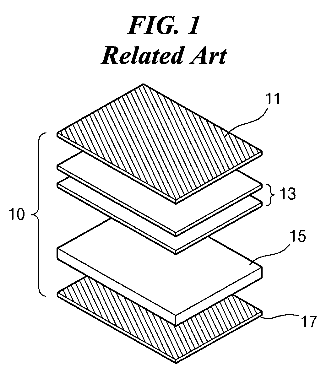
Accordingly, the LCD device 10 in FIG. 1 has an improved viewing angle; however, such an LCD device does not provide multi-viewing modes and does not have convertibility between wide and narrow viewing modes.
In any event, the above-mentioned cell does not perfectly prevent producing images on sides.
As such, the LCD devices according to the related art fail to provide sufficient privacy of a user, even in a narrow viewing angle mode.

Method used


Image

  • Image display device having wide and narrow viewing angle modes and method of driving the same
  • Image display device having wide and narrow viewing angle modes and method of driving the same
  • Image display device having wide and narrow viewing angle modes and method of driving the same

Examples


Embodiment Construction

[0035]Reference will now be made in detail to the preferred embodiments of the invention, examples of which are illustrated in the accompanying drawings.

[0036]FIG. 3 is a cross-sectional view explaining how a viewing zone producing unit for an image display device according to an embodiment of the invention. In FIG. 3, an image display device 110 includes a display panel 120 and a barrier 130. The barrier 130 is disposed in the front of the display panel 120. The display panel 120 generates first and second images “IM1”and “IM2,” and the barrier 130 functions as a viewing zone producing unit. First and second image pixels “PHIM1” and “PIM2” are defined on the display panel 120. The first and second image pixels “PIM1” and “PIM2” may be alternately arranged on the display panel 120. The barrier 130 includes a transmissive portion 132 and a blocking portion 134 to selectively pass light from the first and second image pixels “PIM1” and “PIM2”. All or a substantial amount of light pass...


PUM

PropertyMeasurementUnit
viewing anglesaaaaaaaaaa
luminanceaaaaaaaaaa
areaaaaaaaaaaa

Abstract

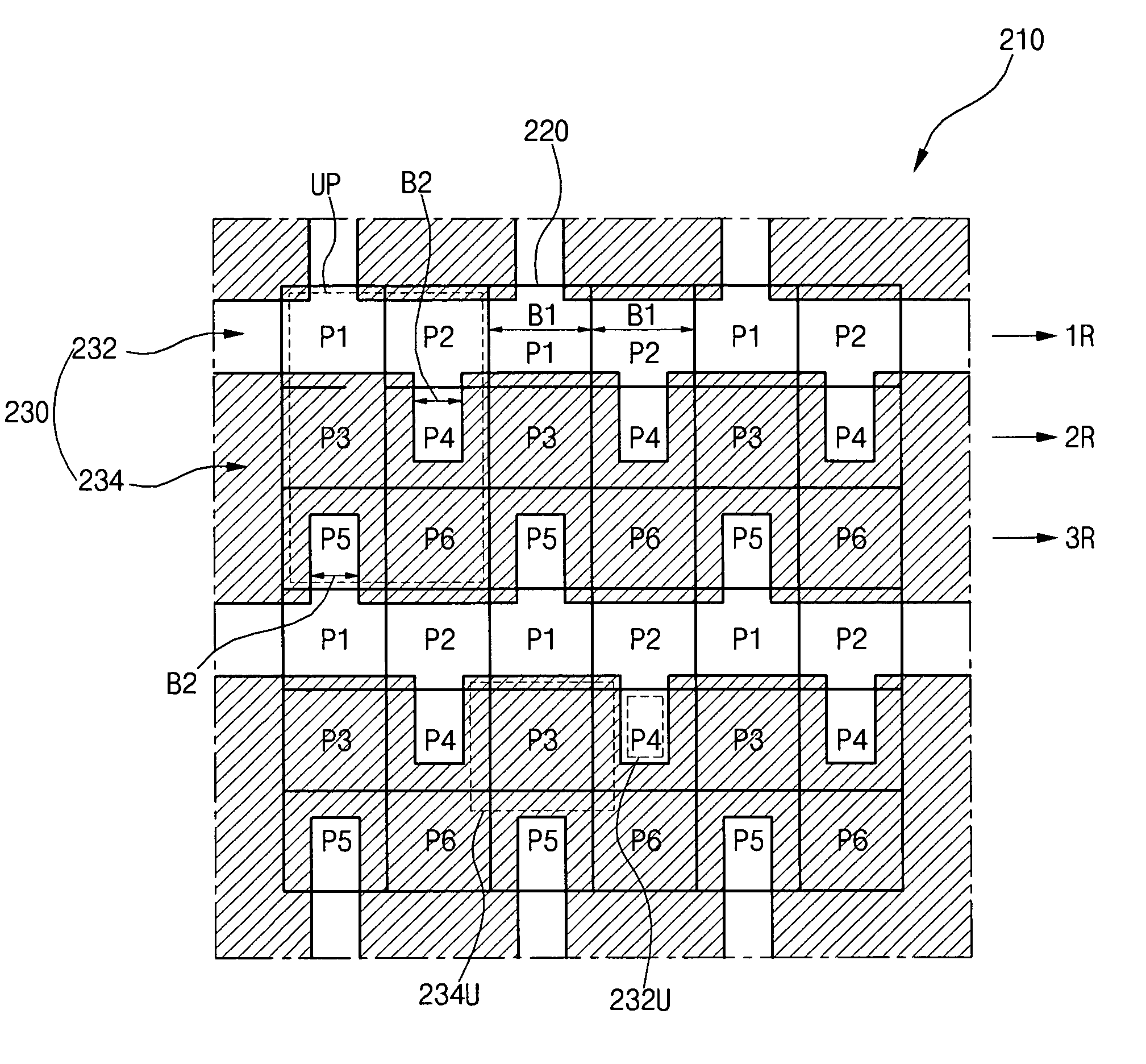
An image display device includes a display panel, and a barrier including a plurality of transmissive portions and a plurality of blocking portions on the display panel, wherein the plurality of transmissive portions and the plurality of blocking portions are arranged in a matrix, wherein 3Nth rows and (3N-1)th rows include the plurality of transmissive portions and the plurality of blocking portions, N being a positive integer, (3N-2)th rows include the plurality of transmissive portions excluding the plurality of blocking portions, , and the transmissive and blocking portions are alternately arranged.

Description

[0001]The invention claims the benefit of Korean Patent Application Nos. 2006-0057987 and 2006-129262, filed in Korea on Jun. 27, 2006 and Dec. 18, 2006, which are hereby incorporated by reference in its entirety.BACKGROUND OF THE INVENTION[0002]1. Field of the Invention[0003]Embodiments of the invention relate to a display device, and more particularly, to a display device and a method of driving the same having wide and narrow viewing modes. Although embodiments of the invention are suitable for a wide scope of applications, they are particularly suitable for providing a display device and a method of driving the same that provide convertibility between wide and narrow viewing angle modes.[0004]2. Discussion of the Related Art[0005]In general, a liquid crystal display (“LCD”) device, which functions as an image display device, includes a first substrate, a second substrate, and a liquid crystal layer. The first and second substrates face each other with a space therebetween, and t...

Claims


Application Information

Patent Timeline
Patent Type & Authority Applications(United States)
IPC IPC(8): G02F1/1343
CPCG02F1/133512G02F1/1323
Inventor HONG, HYUNG-KI
Owner LG DISPLAY CO LTD
Learn More