Modular lamp structure

a module and lamp technology, applied in the field of module lamp structure, can solve the problems of small receiving space of halogen lamps, limited illumination wattage of halogen lamps, and inability to receive larger electronic modules, so as to achieve convenient and easy manner, increase the illumination wattage of lamps, and large space available

Inactive Publication Date: 2007-12-27
HARVATEK CORPORATION
View PDF8 Cites 75 Cited by
  • Summary
  • Abstract
  • Description
  • Claims
  • Application Information

AI Technical Summary

Benefits of technology

[0009] Another object of the invention is to provide a modular lamp structure, the illumination module and the control module are separated by a base, and hence the lamp has a larger space available for receiving larger control modules than was possible in the prior art. The illumination wattage of the lamp can thereby be increased. This allows the user to adjust the brightness and scope of the illumination module in both a convenient and easy manner.

Problems solved by technology

However, the halogen lamp has a small receiving space, and can't receive larger electronic modules.
Hence, the illumination wattage of the halogen lamp is very limited.
Moreover, halogen lamps are usually illuminated for long periods.
In this time they produce large amounts of heat energy, yet lack a heat-dissipating device.
This leads to a short user life, and is inconvenient for users.
Furthermore, the angle and scope of the illumination of the halogen lamp are fixed, so using the halogen lamp is often inconvenient for users.
Accordingly, as discussed above, the prior art still has some drawbacks that could be improved.

Method used


Image

  • Modular lamp structure
  • Modular lamp structure
  • Modular lamp structure

Examples


Embodiment Construction

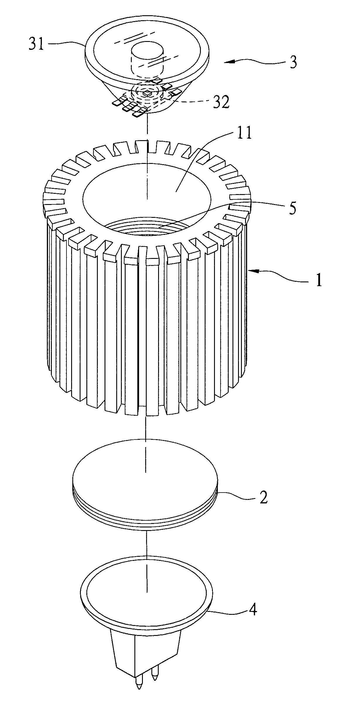
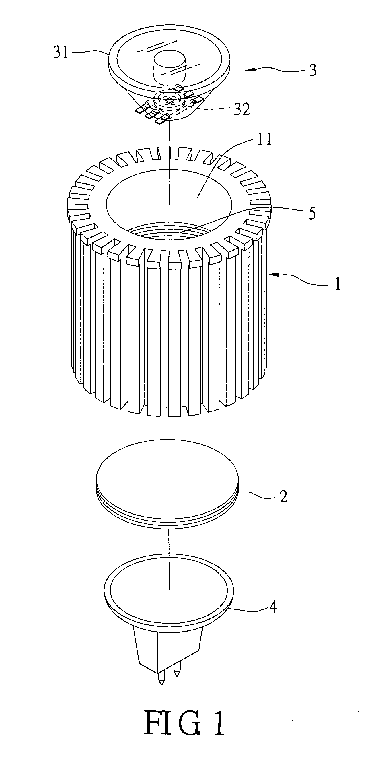
[0018] Reference is made to FIG. 1 and FIG. 2. The present invention of a modular lamp structure includes a housing 1, a base 2, an illumination module 3, and a control module 4. The housing 1 has a receiving space 11 and has fins formed on its exterior side. The housing 1 is a heat-dissipating housing for dissipating the heat generated by the lamp. The housing 1 is cylinder-shaped (it can also be any other shape). The base 2 is disposed in the receiving space 11 and has grooves that act as a screw formed on its side. The illumination module 3 and the control module 4 are separated by the base 2. The base 2 includes one end and one other end. Inside the housing 1 there is an adjusting unit 5, and the base 2 connects to the adjusting unit 5, hence the position of the base 2 is moved via the adjusting unit 5.

[0019] The illumination module 3 is disposed on the one end of the base 2. The illumination module 3 includes a lampshade 31 and a luminescent member 32. The lampshade 31 is a re...


PUM


Abstract

A modular lamp structure includes a housing, a base, an illumination module, and a control module. The housing has a receiving space. The base is disposed in the receiving space, the base including one end and other end. The illumination module is disposed on the one end of the base, and the control module is disposed on the other end of the base, the control module is connected electrically to the illumination module; Thereby the housing is dissipated heat from the lamp module.

Description

BACKGROUND OF THE INVENTION [0001] 1. Field of the Invention [0002] The present invention relates to a lamp structure, and more particularly, to a modular lamp structure. [0003] 2. Description of Related Art [0004] Halogen lamps include a luminescence module and an electronic module. A luminescence module includes a lampshade and a luminescent member. The illumination wattage of the halogen lamp is determined by the electronic module's size. The larger the electronic module, the larger the illumination wattage of the halogen lamp may be. However, the halogen lamp has a small receiving space, and can't receive larger electronic modules. Hence, the illumination wattage of the halogen lamp is very limited. [0005] Moreover, halogen lamps are usually illuminated for long periods. In this time they produce large amounts of heat energy, yet lack a heat-dissipating device. This leads to a short user life, and is inconvenient for users. [0006] Furthermore, the angle and scope of the illumina...

Claims


Application Information

Patent Timeline
Patent Type & Authority Applications(United States)
IPC IPC(8): F21V29/00
CPCF21V14/02F21V23/02F21V29/773F21Y2101/02F21V29/004F21Y2115/10
Inventor WANG, BILYCHUANG, JONNIEWU, SHIH-YU
Owner HARVATEK CORPORATION
Why Eureka
Try Eureka