Fuel tank

a fuel tank and tank body technology, applied in the field of fuel tanks, can solve the problems of complicated fuel tank installation, no longer available space for fuel storage, etc., and achieve the effect of reducing the number of components

Active Publication Date: 2006-10-17
VITESCO TECH GERMANY GMBH
View PDF18 Cites 9 Cited by
  • Summary
  • Abstract
  • Description
  • Claims
  • Application Information

AI Technical Summary

Benefits of technology

[0014]A contribution is made to further reducing the number of components of the fuel tank according to the invention if the base part of the venting device or the attachment of the surge chamber has a

Problems solved by technology

One disadvantage of this is that the installation of the components in the fuel tank beco

Method used


Image

  • Fuel tank
  • Fuel tank
  • Fuel tank

Examples


Embodiment Construction

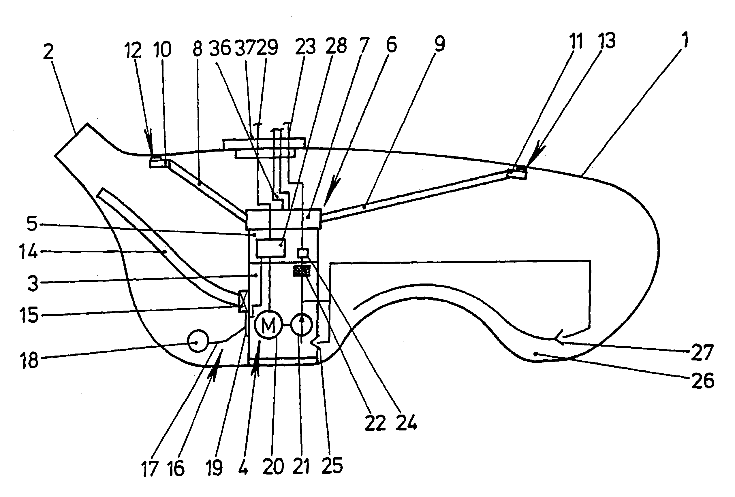
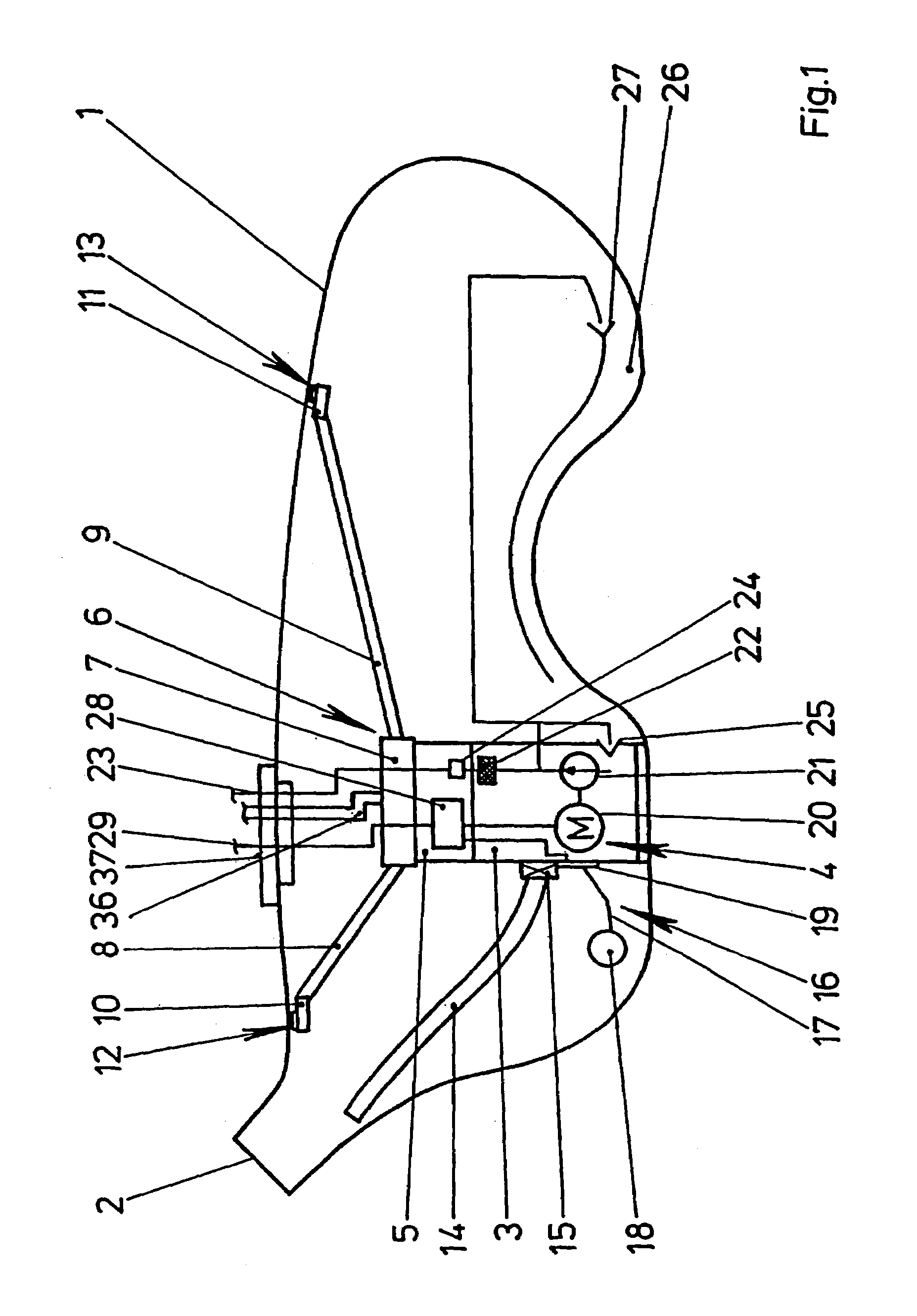
[0020]FIG. 1 shows a fuel tank 1 of a motor vehicle with a filler neck 2 and with a feed unit 4 which is arranged in a surge chamber 3. The surge chamber 3 is fastened to the bottom of the fuel tank 1 and has an attachment 5 for securing a venting device 6. The venting device 6 has a base part 7 fastened on the attachment 5, two side parts 10, 11 which are connected to the base part 7 via lines 8, 9 and are prestressed against the upper wall of the fuel tank 1, and a ventilating and venting line 36 which is guided through a closure 37 closing the fuel tank 1. Openings 12, 13 of the venting device 6 are arranged on the side parts 10, 11. The surge chamber 3 is connected to the filler neck 2 of the fuel tank 1 via a filling line 14. It is therefore ensured that the surge chamber 3 is filled first of all when the fuel tank 1 is being replenished. An overfilling of the surge chamber 3 is prevented by a float-type shutoff valve 15 arranged in the connection of the filling line 14 to the ...


PUM


Abstract

A fuel tank (1) has a constructional unit which can be preassembled and comprises a surge chamber (3) and venting device (6). The constructional unit is fastened to the bottom of the fuel tank (1) and has spring arms for prestressing openings (12, 13), which are provided for venting the fuel tank (1), against the upper wall of the fuel tank (1). The fuel tank (1) can be fitted in a particularly simple manner.

Description

BACKGROUND OF THE INVENTION[0001]The invention relates to a fuel tank having a surge chamber arranged in the bottom region, having a feed unit which sucks up fuel from the surge chamber, having a level sensor for detecting the fuel level in the fuel tank, and having a venting device which is arranged in the upper region of the fuel tank and is intended for venting the fuel tank during operation and / or when replenishing the fuel, the surge chamber, the feed unit and the level sensor being designed as a module which can be fitted outside the fuel tank and can be inserted into the fuel tank.[0002]Fuel tanks of this type are frequently used in motor vehicles today and are known from practice. In this case, the fuel tank is manufactured as a single piece by blow molding or in a number of pieces by injection molding, and has an installation opening for the module. In the case of the fuel tank manufactured by injection molding, first of all at least two shell parts are manufactured and the...

Claims


Application Information

Patent Timeline
IPC IPC(8): F16K24/00B60K15/035B60K15/03F02D33/00F02M37/00F02M37/10
CPCB60K15/03B60K15/035B60K15/03519F02D33/003F02M37/0094F02M37/106B60K2015/03111B60K2015/03118B60K2015/03164B60K2015/03217F02M37/0082B60K2015/03105Y10T137/86228Y10T137/86324
Inventor KROGULL, CHRISTIANREITER, FRANK
Owner VITESCO TECH GERMANY GMBH
Why Eureka
Try Eureka