LED lamp

a technology of led lamps and led chips, which is applied in the field of led lamps, can solve the problems of hard to dissipate heat generated by led lamps, and achieve the effects of saving cost and time of individually packaging led chips, increasing the quantity of led chips able to be arranged in the limited area, and increasing luminosity

Active Publication Date: 2007-12-27
TRANSPACIFIC IP LTD
View PDF3 Cites 26 Cited by
  • Summary
  • Abstract
  • Description
  • Claims
  • Application Information

AI Technical Summary

Benefits of technology

[0011] The central hole is formed on bottom of the lampshade for receiving the axle and the heat pipe passing through. This heat pipe protrudes across both sides of the lampshade. A transparent plate is formed on the opening of the lampshade for enabling the light to pass through while preventing dust, insect or the like entering the lampshade and influencing the service life of the LED chips.
[0014] The characteristics of the invention are that the LED chips are bare chips without packages as prior arts. Therefore, the quantity of LED chips capable of being arranged in the limited area can be increased so as to increase the luminosity. Meanwhile, the cost and time of packaging the LED chips individually are also saved.
[0015] The driving circuit is embedded in the axle for actuating the LED chips individually, controlling the brightness and color blending of the LED lamp, and preventing static electricity to damage the LED chips. The LED chips are electrically connected to the driving circuit through embedding, wire bonding or other methods.
[0016] The heat pipe is installed along the axle for dissipating the heat generated by the LED chips from the heat receiving portion to the heat dissipation portion. The heat pipe is able to transport heat by an evaporation-condensation cycle with the help of porous capillaries. It dissipates the heat at the heat dissipation portion via natural convection or additional cooling fan, and solves the problem of heat accumulation in the LED chips.

Problems solved by technology

There is further a problem that when arranging the LED lamps 100 tightly to get higher luminosity, the heat generated from the LED lamps is hard to be dissipated.

Method used


Image

  • LED lamp
  • LED lamp
  • LED lamp

Examples


first embodiment

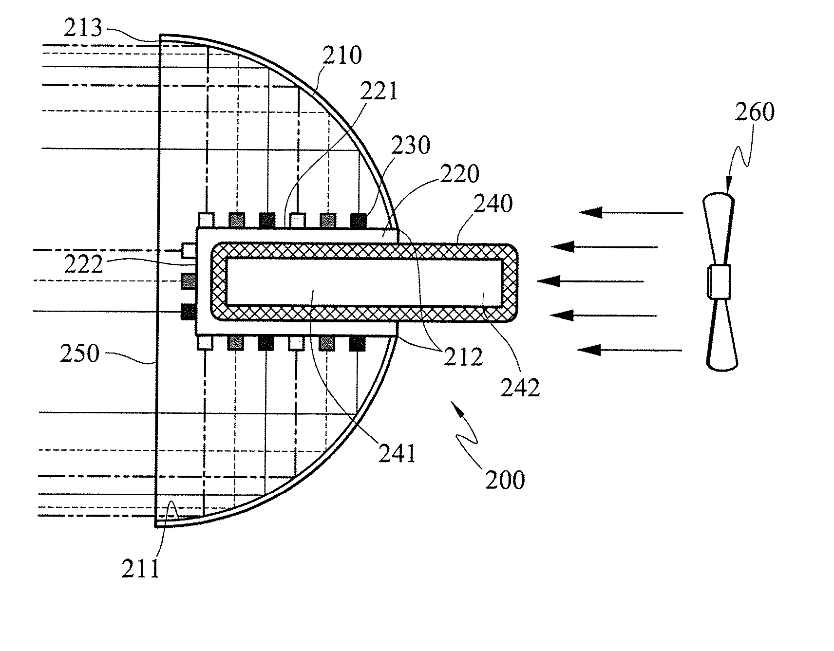
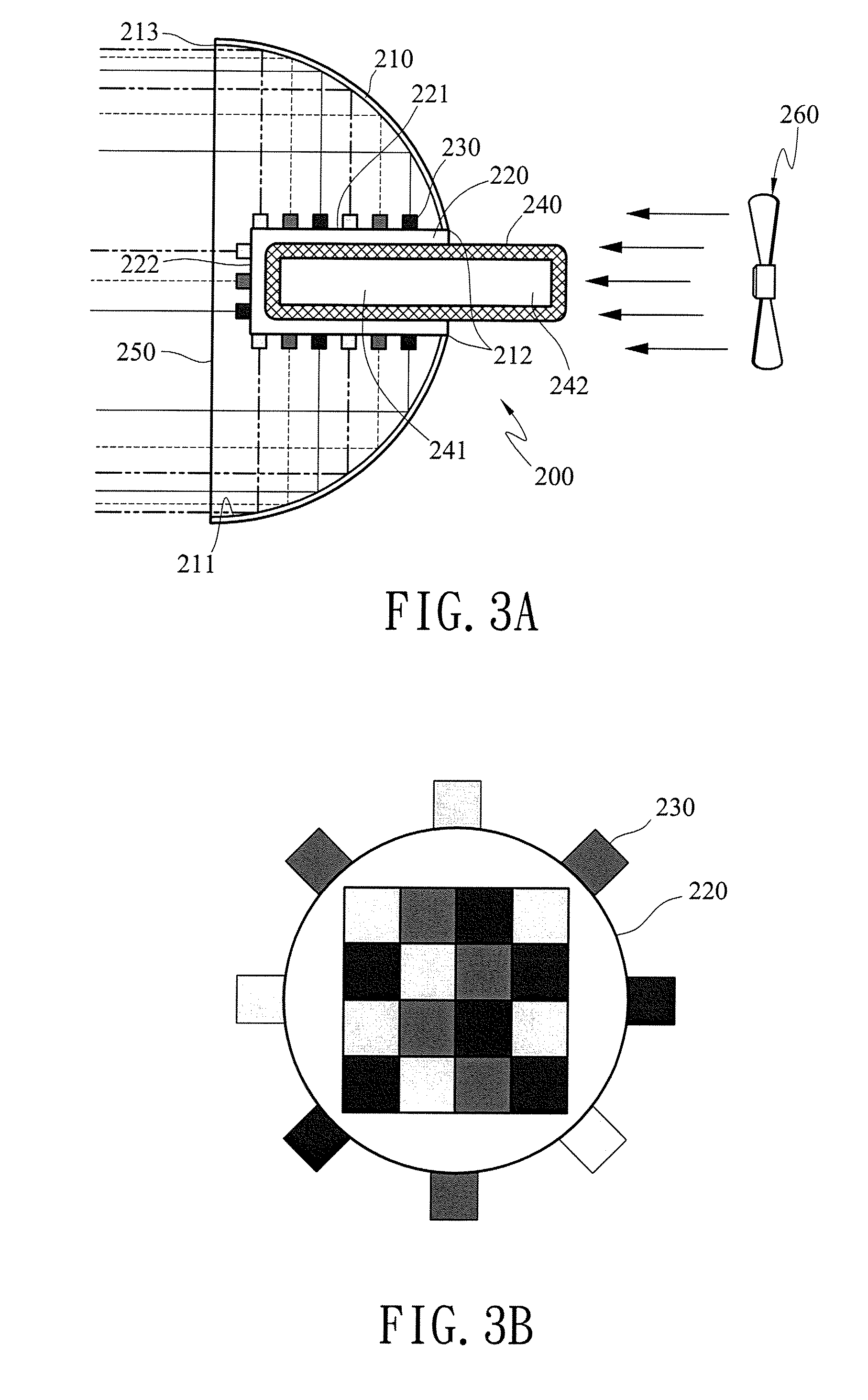
[0032] As shown in FIGS. 3A and 3B, a side view and a front view of an LED lamp in the invention, the LED lamp 200 mainly includes a lampshade 210, an axle 220, LED chips 230, a driving circuit (not shown) and a heat pipe 240.

[0033] The lampshade 210 is a bowl-shaped construction having a concave surface 211, a central hole 212 and an opening 213. The concave surface 211 is used to reflect the light emitted from the LED chips 230 toward the opening 213 of the lampshade 210. To achieve a better reflection, the surface 211 is coated with a reflective film of suitable material or has been polished to reflect light. The central hole 212 is formed on bottom of the lampshade 210 for receiving the axle 220 and the heat pipe 240 passing through.

[0034] A transparent plate 250 is mounted on the opening 213 of the lampshade 210 for enabling the light emitted from the LED chips 230 to pass through while preventing dust, insect or the like entering the lampshade 210 and influencing the service ...

seventh embodiment

[0057]FIGS. 12A and 12B are side view and front view of an LED lamp of the invention. The axle 300 has a different construction from the aforesaid embodiments. The axle 300 is composed of eight heat pipes 301 each having a trapezoid section so as to form the axle 300 an octagon section with a hollow core. An end plate 330 is mounted on front end of the axle 300 and facing the transparent cover 250.

[0058] Of course, the heat pipes 301 of the axle 300 are not limited to the octagon section. They can be of quarters of a circle as shown in FIG. 13, or other sections to form an axle 300 with circular, hexagon or other polygon sections.

[0059] A fluid conduit 3011 is formed inside each heat pipe 301 for performing liquid and gas phase cycles and removing the heat from the LED chips 230. The exterior surface 3012 of each heat pipe 301 is covered with a layer of printed circuit board 310. The driving circuit (not shown in the drawing) is stacked in the printed circuit board 310, or printed ...


PUM


Abstract

An LED lamp includes bare LED chips, an axle, and a lampshade. The bare LED chips are mounted on surface of the axle. The axle extends across the lampshade. A heat pipe is installed inside the axle for transferring the heat generated by the LED chips to exterior of the lampshade and obtaining a better heat dissipation.

Description

FIELD OF THE INVENTION [0001] The invention generally relates to an LED lamp, and in particular relates to an LED lamp applying heat pipe for heat dissipation. BACKGROUND OF THE INVENTION [0002] Light emitting diode (LED) is a highly efficient device to transform electric energy into light in comparison to conventional incandescent bulbs. The most important part of an LED is the semi-conductor chip located in the center of the bulb. The LED chip has two regions separated by a junction. The p region is dominated by positive electric charges, and the n region is dominated by negative electric charges. The junction acts as a barrier to the flow of electrons between the p and the n regions. Only when sufficient voltage is applied to the semi-conductor chip, can the current flow, and the electrons cross the junction into the p region. When an electron moves sufficiently close to a positive charge in the p region, the two charges “re-combine”. Each time an electron recombines with a posit...

Claims


Application Information

Patent Timeline
Patent Type & Authority Applications(United States)
IPC IPC(8): F21V29/00
CPCF21K9/00F21V7/0008F21V29/006F21Y2101/02F21V29/74H05B33/0803H05B33/0857F21V29/004F21V29/677F21Y2111/005F21V29/51F21V29/67F21Y2107/30F21Y2113/13F21Y2115/10H05B45/00H05B45/20
Inventor TAIN, RA-MINLIAU, SHYI-CHINGHO, TZONG-CHE
Owner TRANSPACIFIC IP LTD
Why Eureka
Try Eureka