Coutour-based object recognition method for a monocular vision system

a monocular vision and object recognition technology, applied in the field of surveillance of a stream of monocular video images, can solve the problem of difficult to reliably classify objects in a timely fashion, and achieve the effect of optimal recognition performan

Inactive Publication Date: 2007-12-27
DELPHI TECH INC
View PDF9 Cites 14 Cited by
  • Summary
  • Abstract
  • Description
  • Claims
  • Application Information

AI Technical Summary

Benefits of technology

[0004]The present invention is directed to an improved object recognition method in which the contours (i.e., outlines or profiles) of an imaged object is identified, characterized by wavelets and slope sequence, and compared to sets of stored contours. If a match of sufficiently high confidence is not found, the image is distorted to simulate an incrementally di

Problems solved by technology

However, the extracted edge data contains a significant amount of extraneous information that varies significantly wit

Method used


Image

  • Coutour-based object recognition method for a monocular vision system
  • Coutour-based object recognition method for a monocular vision system
  • Coutour-based object recognition method for a monocular vision system

Examples


Embodiment Construction

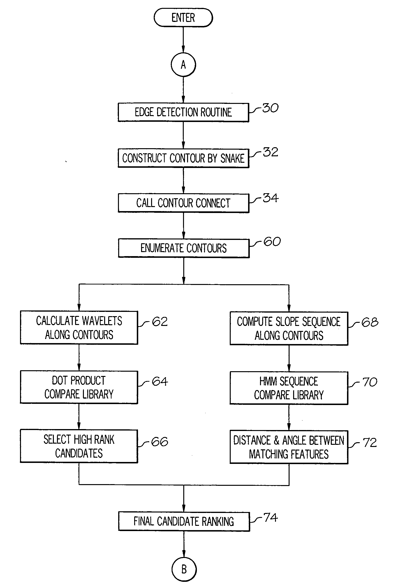
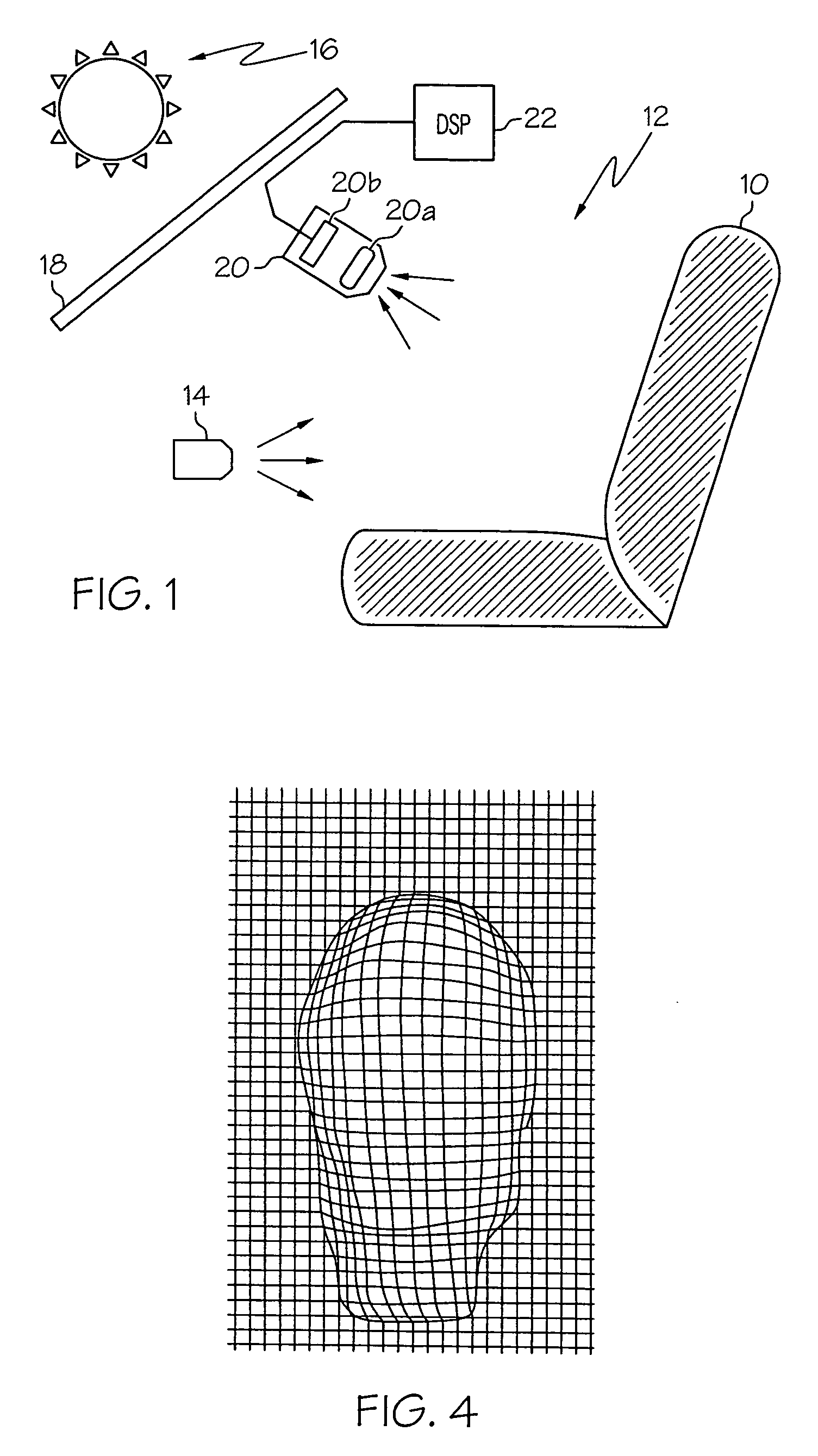
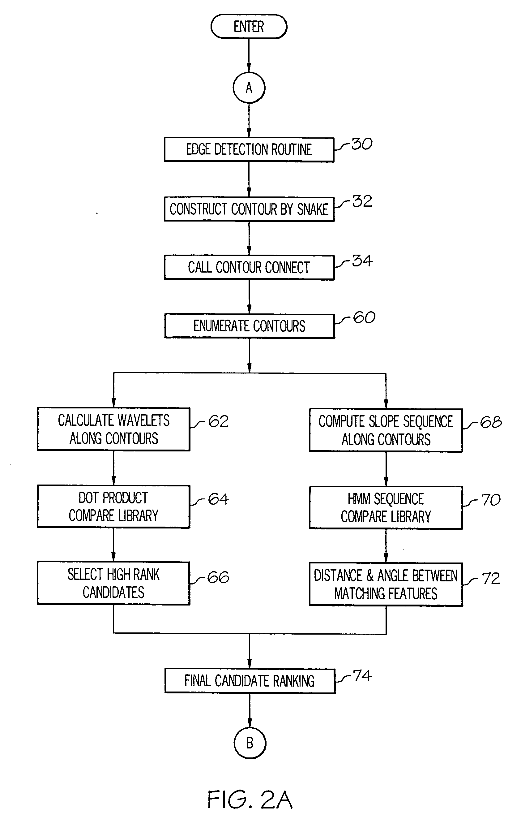
[0009]The method of the present invention is described herein in the context of a vision-based vehicle occupant recognition system, but it should be recognized that the method is equally applicable to other object recognition systems, whether vehicular or non-vehicular. Referring to FIG. 1, the vehicle environment includes a passenger seat 10 mounted in a cabin 12. The seat 10 is illuminated by both an active light source 14 and an ambient light source, as designated by sun 16. The active light source 14 may be one or more light emitting diodes that emit light in a visible or near-infrared wavelength band from a central location such as the interior rear-view mirror (not shown). The ambient light source may be solar as indicated, or may emanate from other sources such as roadside lights, and typically enters the cabin 12 through a window 18.

[0010]The cabin 12 is equipped with a monocular occupant recognition system including the active light source 14, a digital camera (DC) 20 and a...


PUM


Abstract

An object recognition method analyzes an imaged object based on its contour. Extracted contours are characterized by wavelets and slope sequence, and compared to sets of stored contours to recognize a known feature. If a match of sufficiently high confidence is not found, the image is distorted to simulate an incrementally different perspective of the imaged object, and the process of contour identification, characterization and comparison is repeated until a match of sufficiently high confidence is found. The cycle of image distortions allow two-dimensional images obtained from a monocular vision system to be analyzed for three-dimensional motion for optimal recognition performance.

Description

TECHNICAL FIELD[0001]The present invention relates to monitoring a stream of monocular video images, and more particularly to a method of recognizing an imaged object based on its contour.BACKGROUND OF THE INVENTION[0002]Occupant recognition and classification systems are commonly used in motor vehicles for determining if pyrotechnically deployed restraints such as air bags should be deployed in the event of a sufficiently severe crash. Although most current production systems rely exclusively on sensors for measuring physical parameters such as seat force and object proximity, vision-based systems have become economically attractive due to the advent of low-cost digital signal processors and solid-state imaging chips. See, for example, the U.S. Pat. No. 6,801,662 and the U.S. Publication No. 2003 / 0204384 to Owechko et al., and the U.S. Publication No. 2006 / 0088219 to Zhang et al., each of which is incorporated by reference herein. As disclosed by Owechko et al. and Zhang et al., ob...

Claims


Application Information

Patent Timeline
IPC IPC(8): G06K9/00G06K9/48G06K9/40
CPCG06K9/6206G06K9/6204G06V10/752G06V10/754
Inventor SCHUBERT, PETER J.
Owner DELPHI TECH INC
Why Eureka
Try Eureka