Fan speed change control

a fan speed change and control technology, applied in the direction of electrical apparatus construction details, machine/engine, engine starters, etc., can solve the problem of user's perceived noise level being higher

Inactive Publication Date: 2007-12-27
WINBOND ELECTRONICS CORP
View PDF50 Cites 61 Cited by
  • Summary
  • Abstract
  • Description
  • Claims
  • Application Information

AI Technical Summary

Benefits of technology

[0011]According to the present invention, there is also provided: a system for controlling a speed of a fan for an electronic system, comprising: a temperature monitoring and fan control module, wherein the temperature monitoring and fan control module is configured to receive a plurality of temperature readings relating to the electronic system associated with a fan, configured for each of the plurality of received temperatures to calculate a value of a variable relating to fan speed or a function thereof corresponding to the each received temperature; configured to select a value of a variable or a function thereof which would lead to a highest fan speed out of the calculated values; and configured to output a control signal reflecting the selection.
[0012]According to the present invention, there is further provided: a system for controlling a speed of a fan for an electronic system including a central processing unit, comprising: a temperature monitoring and fan control module, external to the central processing unit, configured to receive a temperature relating to the electronic system; configured to check whether the temperature has a predetermined relationship with a predetermined temperature level or range; and configured to adjust at least one parameter which affects fan speed, if the temperature has a predetermined relationship; wherein the at least one parameter is selected from a group comprising: slope of a range where a variable relating to fan speed is proportional to temperature, slope of a range where duty cycle is proportional to temperature, maximum value of a variable relating to fan speed, maximum duty cycle, minimum value of a variable relating to fan speed, minimum duty cycle, predetermined level where adaptation occurs, predetermined range where adaptation occurs, predetermined relationship to be checked, impact of time duration during which a predetermined relationship holds on adaptability, correspondence between ambient temperatures and parameters, correspondence between value of a variable relating to fan speed and temperature direction, correspondence between value of a variable relating to fan speed and temperature change, correspondence between value of a variable relating to fan speed and rate of temperature change, and correspondence between value of the variable relating to fan speed with time temperature is at a same level or range.

Problems solved by technology

In many electronic systems with fans, more frequent and / or more drastic changes in the speed of the fan result in a higher perceived noise level for the user.

Method used


Image

  • Fan speed change control
  • Fan speed change control
  • Fan speed change control

Examples


Embodiment Construction

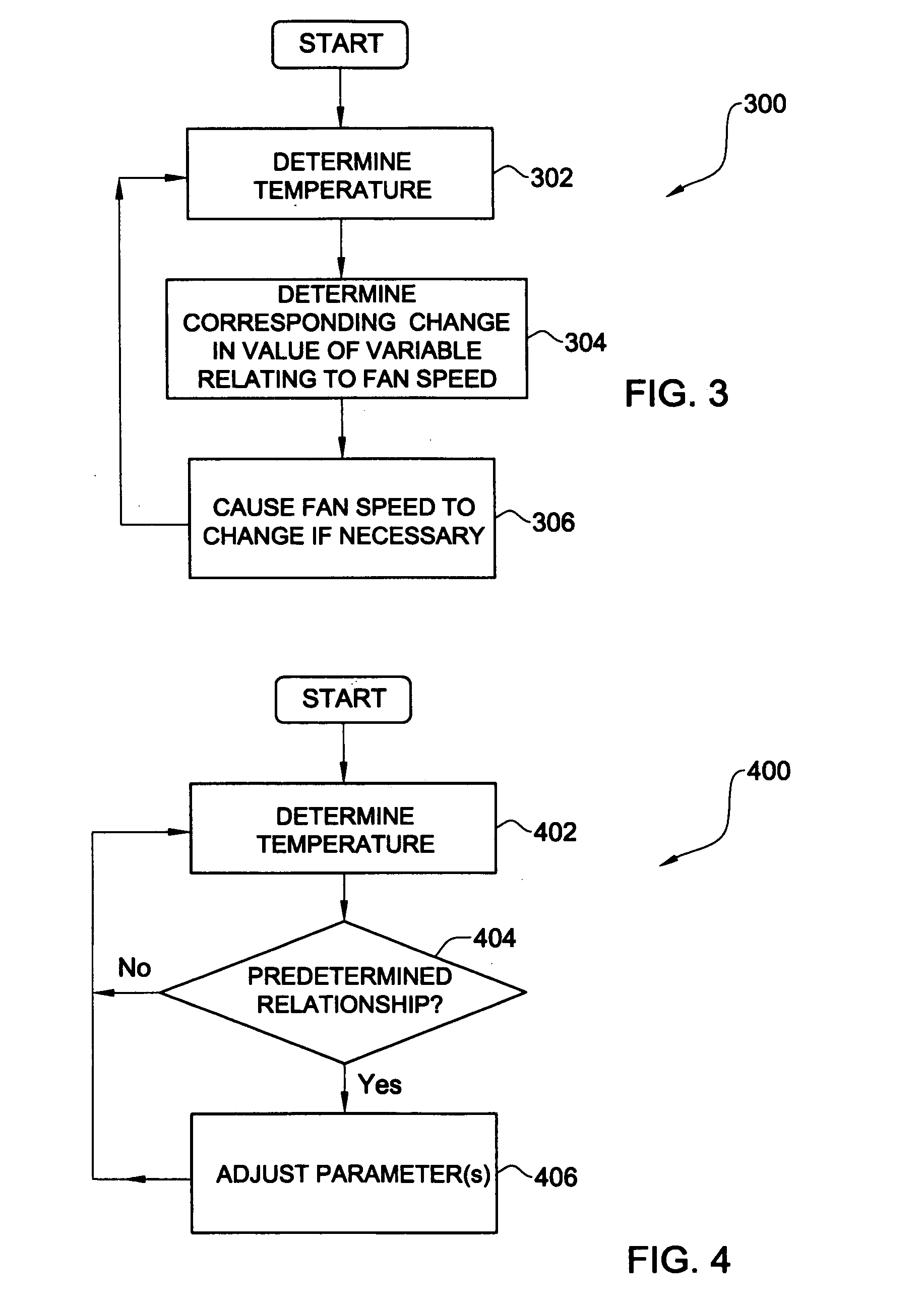
[0029]Described herein are embodiments of the current invention for fan speed control.

[0030]As used herein, the phrase “for example,”“such as” and variants thereof describing exemplary implementations of the present invention are exemplary in nature and not limiting.

[0031]The term change as used herein should be construed to include zero and / or non-zero change, as appropriate. A nonzero change can be positive and / or negative, as appropriate.

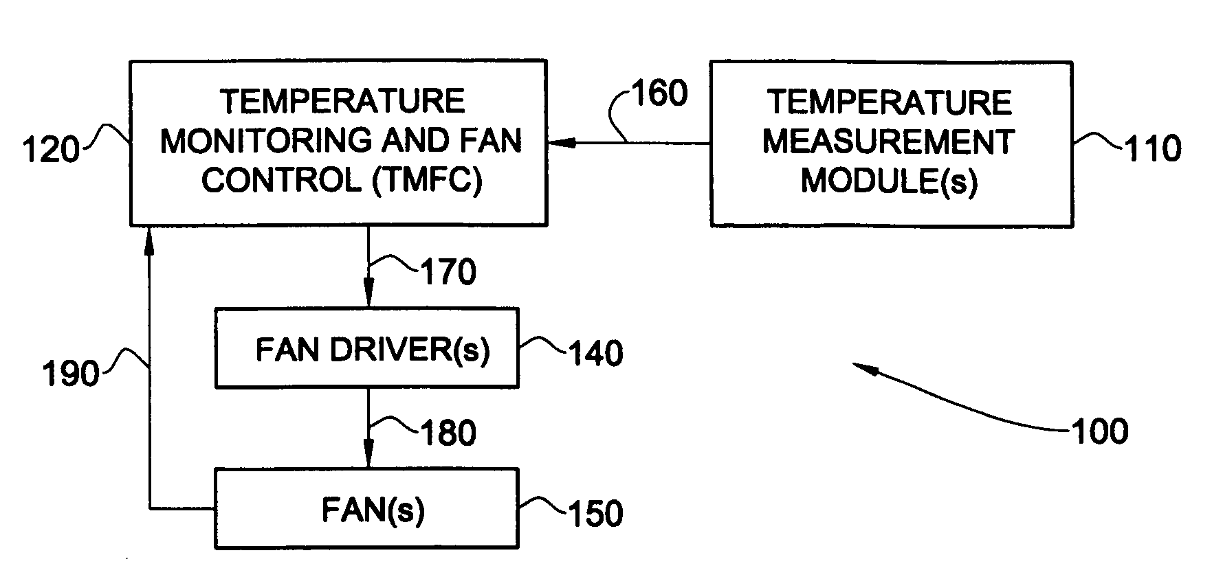
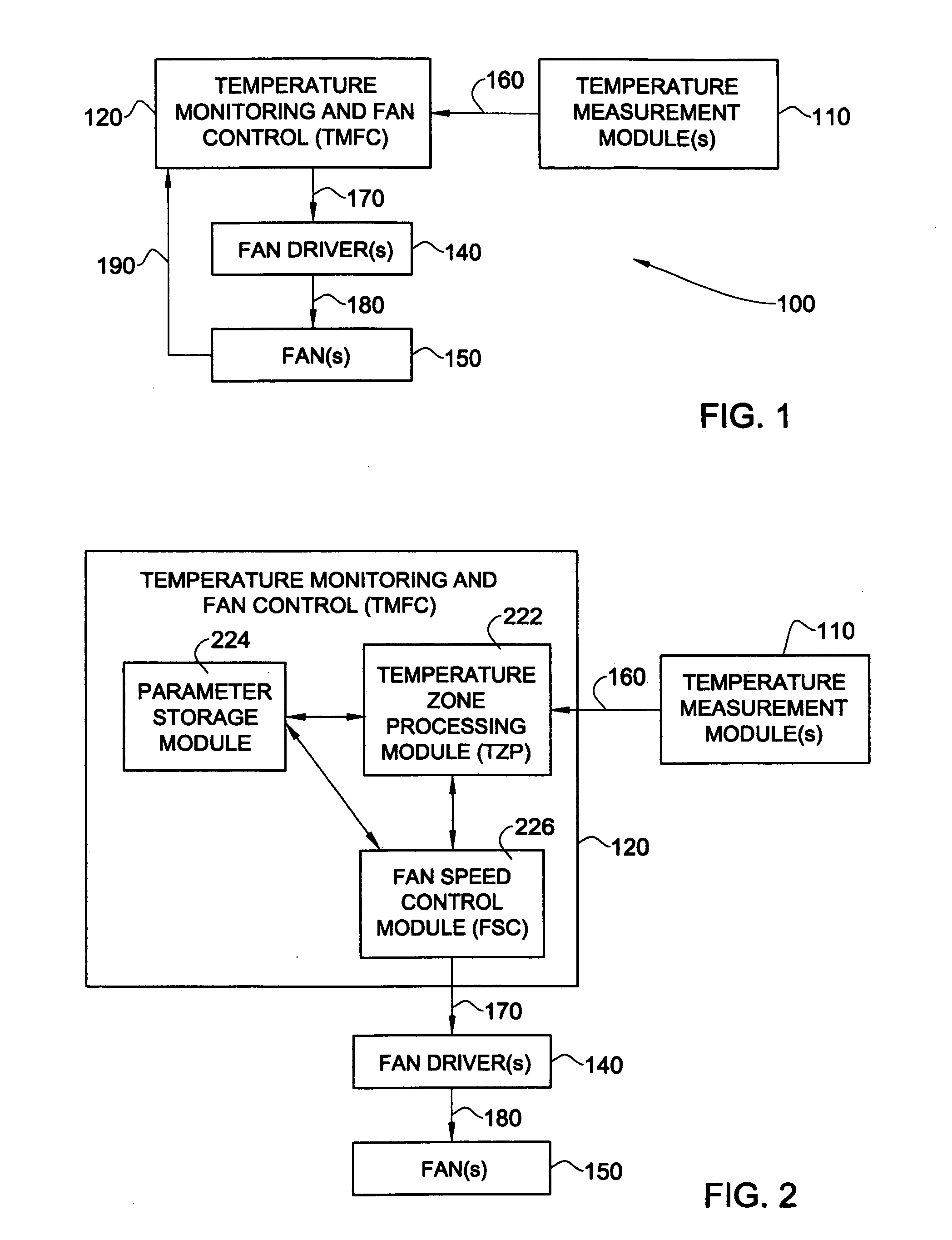
[0032]Refer to FIG. 1 which shows a system 100 for fan speed control, according to an embodiment of the present invention. In one embodiment, parts or all of system 100 can be placed anywhere within and / or outside an electronic system in order to attempt to control the temperature of the electronic system. The illustrated system 100 includes one or more temperature measurement module(s) 110, a temperature monitoring and fan control module TMFC 120, one or more fan driver(s) 140 and one or more fans 150. Each of temperature measurement module(s) 1...


PUM


Abstract

Methods and systems for controlling the speed of a fan for an electronic system. In some embodiments of the invention, temperatures are associated with changes in the value of a variable relating to fan speed. In one of these embodiments, there is a range of temperatures where the fan speed is fixed. In one embodiment of the invention, where there is a plurality of temperature readings associated with a fan, the temperature reading which would result in the highest fan speed is operative. In one embodiment of the invention, the fan speed control is capable of automatic self-adjustment.

Description

FIELD OF THE INVENTION[0001]The invention relates to temperature monitoring and fan control systems.BACKGROUND OF THE INVENTION[0002]Temperature control is important in many electronic systems, including, for example, computers. Fans are sometimes included in an electronic system so that the air from the fan can cool off the electronic system when necessary. In many electronic systems with fans, more frequent and / or more drastic changes in the speed of the fan result in a higher perceived noise level for the user.SUMMARY OF THE INVENTION[0003]According to the present invention, there is provided: a method of controlling a speed of a fan for an electronic system comprising: determining a temperature relating to the electronic system; determining a change in a value of a variable relating to fan speed which corresponds to the determined temperature; and if there is a nonzero determined corresponding change in a value of the variable relating to fan speed, causing the speed of a fan to...

Claims


Application Information

Patent Timeline
Patent Type & Authority Applications(United States)
IPC IPC(8): F04D15/00H05K7/20
CPCF04D25/166H05K7/20209F04D27/004Y02B30/70
Inventor ALON, MOSHETASHER, NIRALBAZ, LIOR
Owner WINBOND ELECTRONICS CORP
Why Eureka
Try Eureka