Exhaust gas stack

a technology of exhaust gas stack and exhaust gas, which is applied in the direction of combustion process, combustion treatment, building components, etc., can solve the problems of reducing the noise level of the environment, affecting the efficiency of the exhaust system, and affecting the operation of the exhaust system

Inactive Publication Date: 2007-12-27
M & I POWER TECH
View PDF22 Cites 12 Cited by
  • Summary
  • Abstract
  • Description
  • Claims
  • Application Information

AI Technical Summary

Benefits of technology

[0007]The present disclosure provides an advantageous exhaust gas stack for emitting exhaust gases into the atmosphere and an advantageous velocity control apparatus for use at the top end of an exhaust stack which is able to adjust or control the exit velocity of exhaust gases. As will be apparent from the following detailed description and appended figures that follow, the present disclosure provides, inter alia, the following advantageous advances to the field of stacks or chimneys for exhaust gases:
[0010](c) An exhaust gas stack that provides energy efficiency as it can permit the use of an exhaust fan powered by a smaller motor, i.e. lower horsepower motor than the fan / motor combination required by a conventional exhaust gas stack designed for similar exhaust airflow rates.
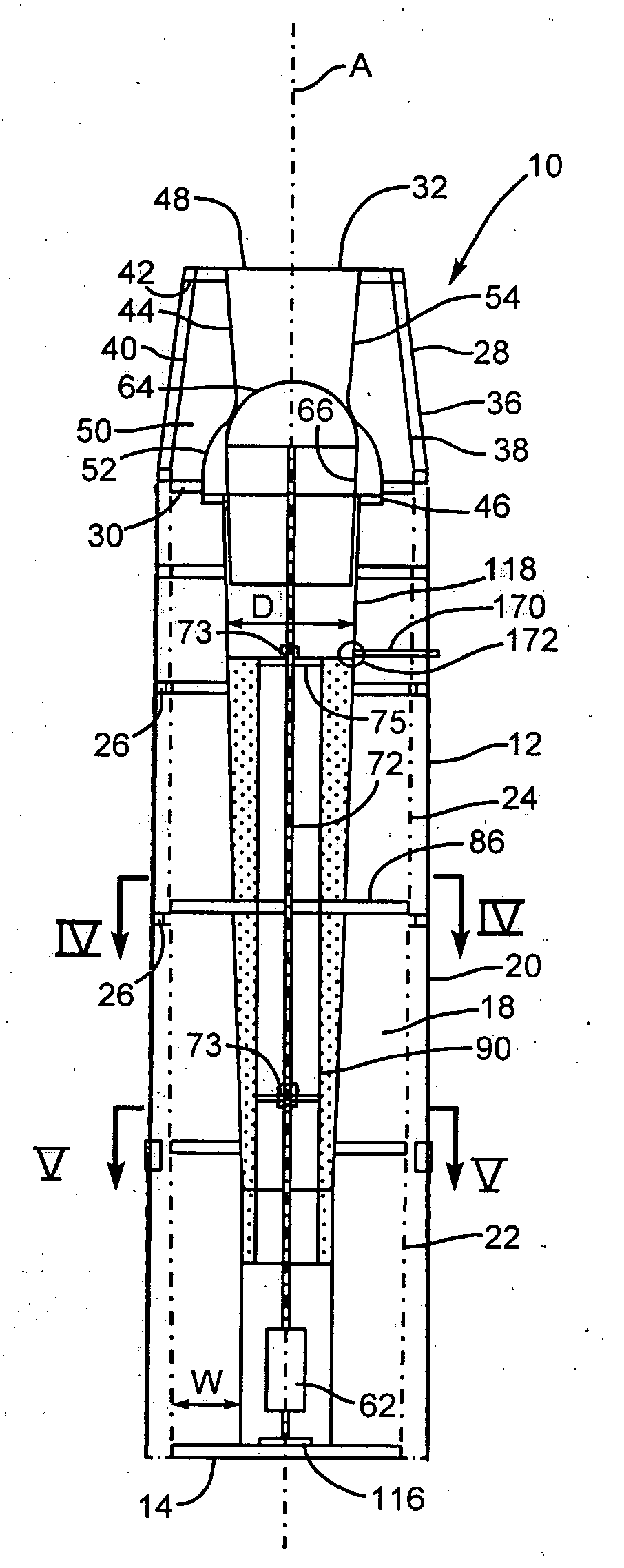
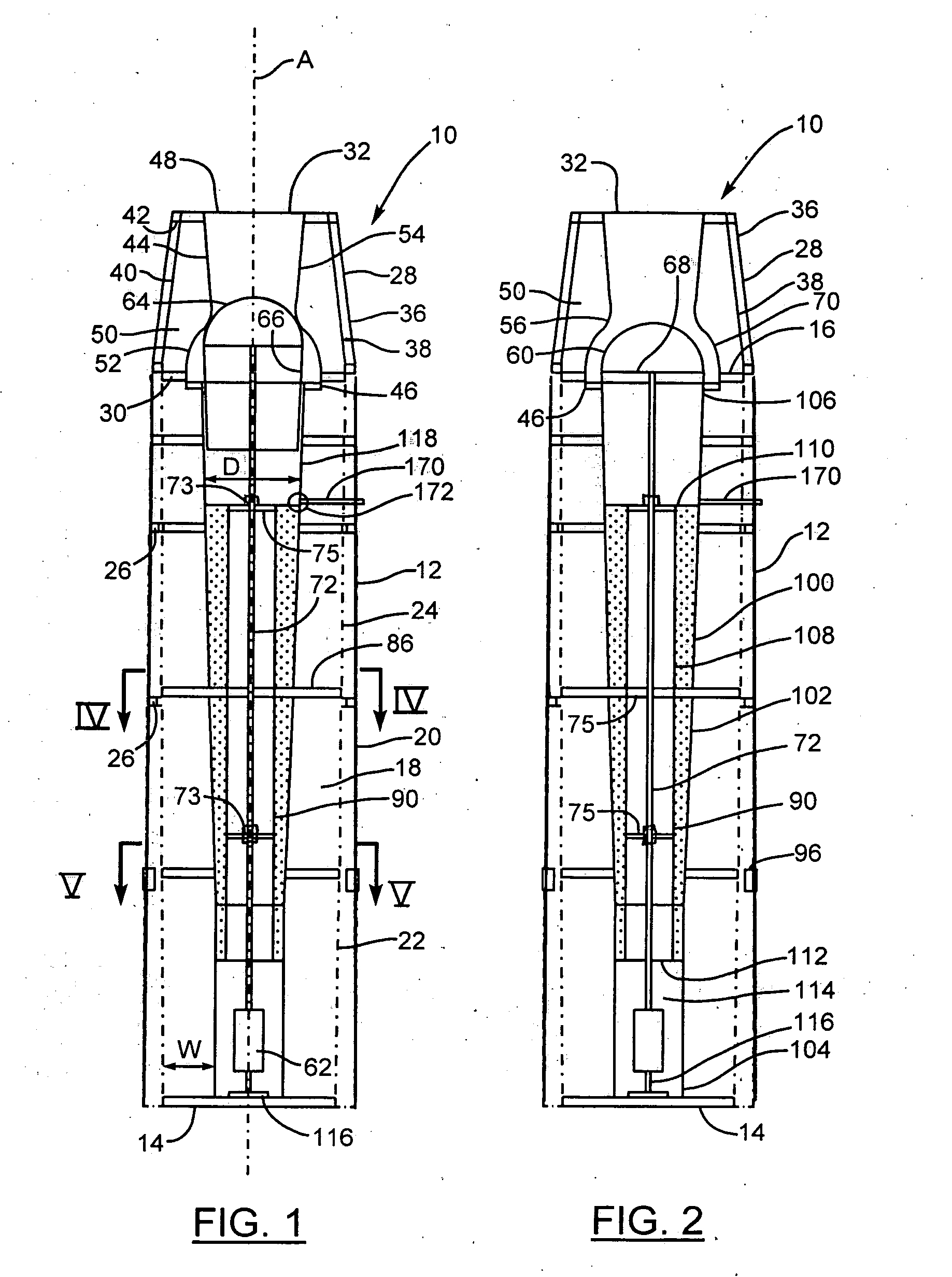
[0011]According to an exemplary embodiment of the present disclosure, an exhaust gas stack comprises an elongate, tubular stack member having an inlet end, an outlet end, a central longitudinal first axis and an exhaust gas passage extending between the inlet and outlet ends. The stack member is adapted to extend vertically with the inlet end being a bottom end when the exhaust gas stack is installed for use. An end section is mounted on the outlet end and has an open first end, an open second end of small diameter than the first end, and a frustoconical passage extending between the first and second ends. The first end is connected to the outlet end of the stack member. An inner duct section, which is substantially circular in transverse cross-section, has a first duct end, an open second duct end, and a central longitudinal axis co-axial with the first axis. The duct section is mounted centrally in the passage of the end section whereby an annular gas flow passage is formed between the duct section and the end section. The duct section has a first axial portion adjacent the first duct end and a second axial portion adjacent the second duct end with the two axial portions meeting at an annular junction of reduced diameter relative to the diameter of the first axial portion at the first duct end. An air plug member is movable between an open position at which exhaust gases can flow past the plug member and through the inner duct section and another position at which the plug member restricts or prevents flow of exhaust gases through the inner duct section. An actuator is connected to the plug member and is capable of moving the plug member between the open position and the closed position.
[0013]According to another exemplary embodiment of the present disclosure, a velocity control apparatus for use at a top end of an exhaust fan includes a hollow member adapted for mounting on the top end of the exhaust stack and having an open first end, an open second end of smaller diameter than the first end, and a frustoconical passage extending between the first and second ends. The first end of this member is connected to the top end of the stack during use of the apparatus. An inner duct section is also provided and this section has a first duct end, an open second duct end, and a central longitudinal axis which is aligned with the central longitudinal axis of the exhaust stack when the apparatus is mounted on the exhaust stack. The duct section is mounted centrally in the hollow member whereby an annular gas flow passage is formed between the duct section and the hollow member. An air plug member is movable between an open position at which the exhaust gases can flow past the plug member and through the inner duct section and another position at which the plug member restricts or prevents flow of the exhaust gases through the inner duct section and thereby at least reduces the amount of exhaust gases flowing through the inner duct section during use of this apparatus. The apparatus includes an actuator connected to the plug member and adapted to move the plug member between the open and another position.

Problems solved by technology

As the exhaust air quantity drops, these dampers are opened to introduce outside air into the fan inlet chamber so that the fan delivers constant airflow at all times. However, the operation of this exhaust system is not energy efficient.
Another concern with a standard exhaust stack design is the amount of noise that eminates from the exhaust stack.
This is becoming a more significant problem for industry and for laboratories because the allowable noise levels that can be radiated to the environment is becoming more restricted by local by-laws and other legislation.

Method used


Image

  • Exhaust gas stack
  • Exhaust gas stack
  • Exhaust gas stack

Examples


Embodiment Construction

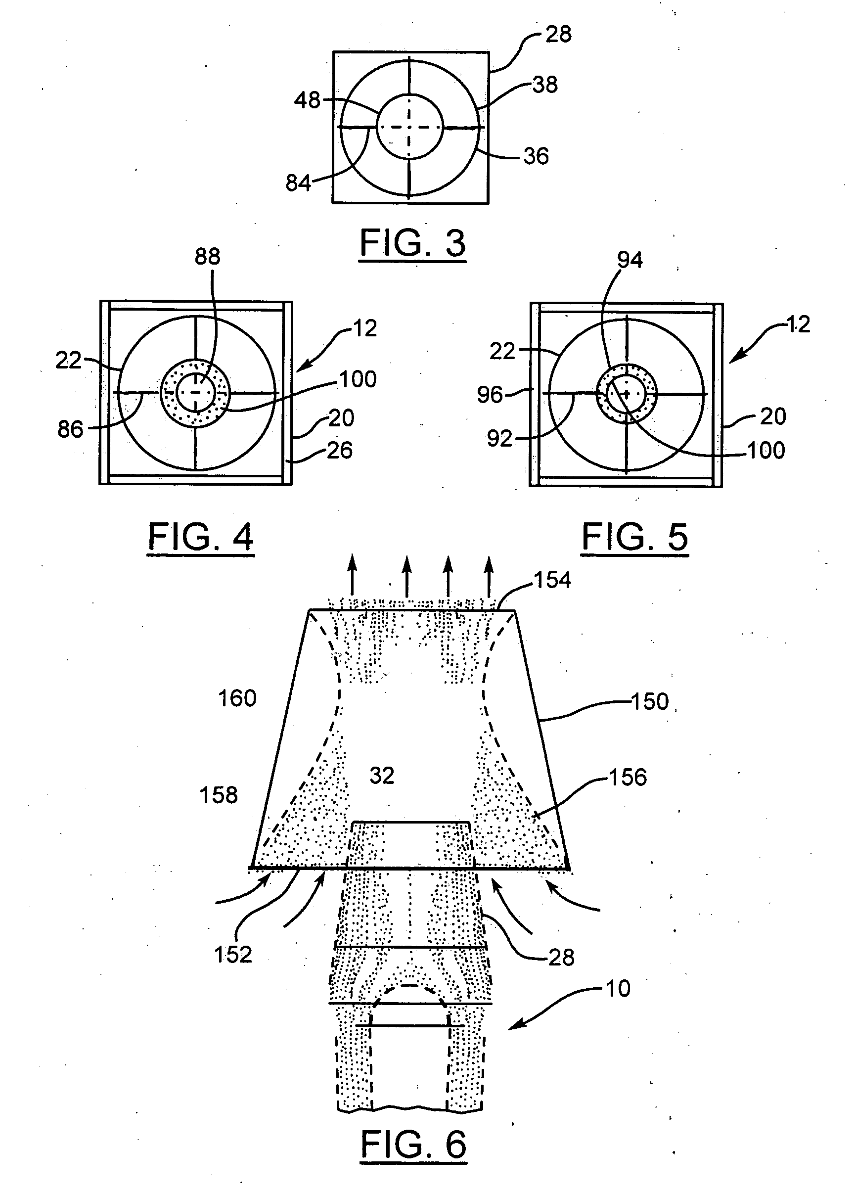
[0026]FIGS. 1 and 2 illustrate one exemplary embodiment of an exhaust gas stack constructed in accordance with the present disclosure. This exhaust gas stack includes an elongate, tubular stack member 12 having an inlet end 14, an outlet end 16, a central longitudinal first axis indicated at A and exhaust gas passage 18 extending between the inlet and outlet ends. The stack member is adapted to extend vertically with the inlet end being a bottom end when the stack is installed for use. The illustrated embodiment of the stack member has an exterior wall 20 which can be made of imperforate sheet metal such as sheet steel having sufficient thickness and strength to support the weight of the stack and external forces acting thereon such as wind. The illustrated stack member 12 has a square, horizontal cross-section defined by this exterior wall but it will be appreciated that the exterior horizontal cross-section can also be circular along the entire length of the stack member. Spaced i...


PUM


Abstract

An exhaust gas stack includes an elongate, tubular stack member having inlet and outlet ends and a central longitudinal axis. An end section is mounted on the outlet end and has open first and second ends, the first end connected to the outlet end of the stack member and a frustoconical passage extending between these ends. An inner duct section has a central axis co-axial with the axis of the stack member and is mounted centrally in the end section. An annular gas passage is formed between the duct section and the end section. An air plug is movable between an open position at which exhaust gases can flow through the inner duct section and another position at which the plug restricts or prevents passage of exhaust gases through this duct section. An actuator is connected to the plug in order to move it between an open and other positions.

Description

BACKGROUND OF THE INVENTION[0001]The present disclosure is directed to exhaust gas stacks and to apparatus and devices for controlling the velocity of exhaust gases exiting from exhaust stacks.[0002]A variety of exhaust gas stacks and exhaust ducts are known in industry for the purpose of exhausting gases from sources such as furnaces. Vertical exhaust stacks can vary in height and in some cases can be of substantial height. Existing conventional exhaust gas stacks are generally constant geometry (fixed discharge area) devices. In many cases, such stacks are sized so as to maintain approximately 4,000 fpm velocity at the stack discharge at the maximum flow rate for the particular exhaust application in order to diffuse the exhaust gases into the atmosphere as required by local building codes.[0003]With a conventional stack design, the velocity of the gases at the stack discharge will drop when the airflow volume changes to lower than maximum since the discharge area of the stack rem...

Claims


Application Information

Patent Timeline
Patent Type & Authority Applications(United States)
IPC IPC(8): E04F17/02F23J11/00
CPCE04F17/02F23L17/02F23J2900/13003F23J13/08
Inventor DATTA, DIPTI
Owner M & I POWER TECH
Why Eureka
Try Eureka